


8
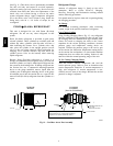
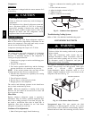
(See Fig. 11.) This check valve is permanently assembled
into this core body and cannot be serviced separately;
replace the entire core body if necessary. Service tools are
available from RCD that allow the replacement of the
check valve core without having to recover the entire
system refrigerant charge. Apply compressor refrigerant
oil to the check valve core’s bottom o--ring. Install the
fitting body with 96 +/ --10 in--lbs of torque; do not
overtighten.
PURONR (R--410A) REFRIGERANT
This unit is designed for use with Puron (R--410A)
refrigerant. Do not use any other refrigerant in this
system.
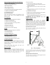
Puron (R--410A) refrigerant is provided in pink (rose)
colored cylinders. These cylinders are available with and
without dip tubes; cylinders with dip tubes will have a
label indicating this feature. For a cylinder with a dip
tube, place the cylinder in the upright position (access
valve at the top) when removing liquid refrigerant for
charging. For a cylinder without a dip tube, invert the
cylinder (access valve on the bottom) when removing
liquid refrigerant.
Because Puron (R--410A) refrigerant is a blend, it is
strongly recommended that refrigerant always be removed
from the cylinder as a liquid. Admit liquid refrigerant into
the system in the discharge line. If adding refrigerant into
the suction line, use a commercial metering/expansion
device at the gauge manifold; remove liquid from the
cylinder, pass it through the metering device at the gauge
set and then pass it into the suction line as a vapor. Do not
remove Puron (R--410A) refrigerant from the cylinder as a
vapor.
Refrigerant Charge
Amount of refrigerant charge is listed on the unit’s
nameplate. Refer to Carrier GTAC2--5 Charging,
Recovery, Recycling and Reclamation training manual
and the following procedures.
Unit panels must be in place when unit is operating during
the charging procedure.
No
Charge
Use standard evacuating techniques. After evacuating
system, weigh in the specified amount of refrigerant.
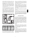
Low--Charge
Cooling
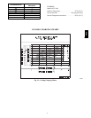
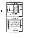
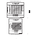
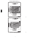
Using Cooling Charging Charts, Fig. 12, vary refrigerant
until the conditions of the appropriate chart are met. Note
the charging charts are different from type normally used.
Charts are based on charging the units to the correct
superheat for the various operating conditions. Accurate
pressure gauge and temperature sensing device are
required. Connect the pressure gauge to the service port
on the suction line. Mount the temperature sensing device
on the suction line and insulate it so that outdoor ambient
temperature does not affect the reading. Indoor--air cfm
must be within the normal operating range of the unit.
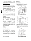
To Use Cooling Charging
Charts
Take the outdoor ambient temperature and read the
suction pressure gauge. Refer to chart to determine what
suction temperature should be. If suction temperature is
high, add refrigerant. If suction temperature is low,
carefully recover some of the charge. Recheck the suction
pressure as charge is adjusted.
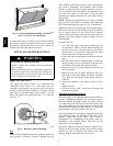
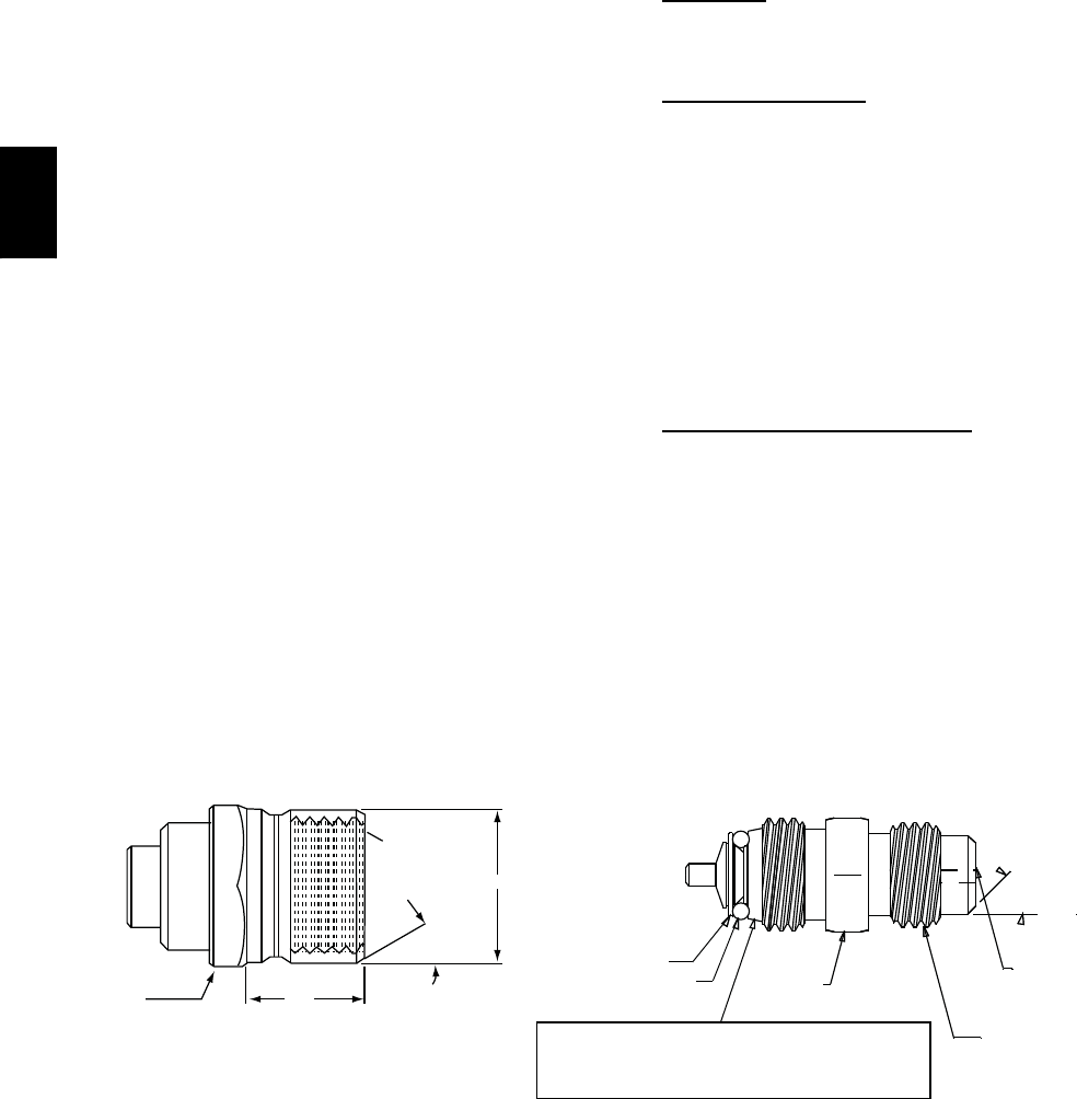
1/2-20 UNF RH
30
0.596
.47
5/8” HEX
SEAT
CORE
WASHER
DEPRESSOR PER ARI 720
+.01/-.035
FROM FACE OF BODY
7/16-20 UNF RH
O-RING
45
torqued into the seat. Appropriate handling is
required to not scratch or dent the surface.
1/2" HEX
This surface provides a metal to metal seal when
o
o
(Part No. EC39EZ067)
C08453
Fig. 11 -- CoreMax Access Port Assembly
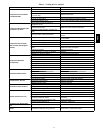
48TC