


18
A
E
F
C
D
B
C08246
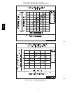
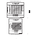
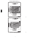
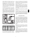
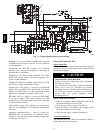
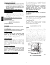
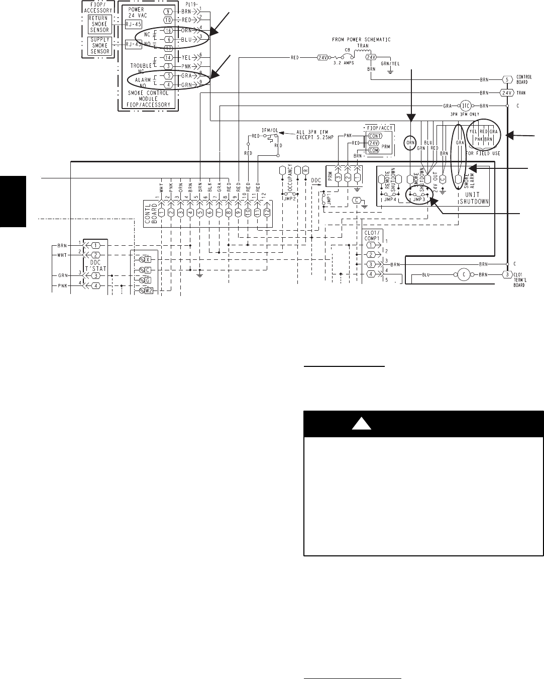
Fig. 23 -- Typical Smoke Detector System Wiring
Highlight C: 24--v power signal via ORN lead is removed
at Smoke Detector input on LCTB; all unit operations
cease immediately.
PremierLink and RTU--MP Controls: Unit operating
functions (fan, cooling and heating) are terminated as
described above. In addition:
Highlight D: On smoke alarm condition, the smoke
detector NO Alarm contact will close, supplying 24--v
power to GRA conductor.
Highlight E: GRA lead at Smoke Alarm input on LCTB
provides 24--v signal to FIOP DDC control.
Premier--Link: This signal is conveyed to PremierLink
FIOP’s TB1 at terminal TB1--6 (BLU lead). This signal
initiates the FSD sequence by the PremierLink control.
FSD status is reported to connected CCN network.
RTU--MP: The 24--v signal is conveyed to RTU--MP’s
J1--10 input terminal. This signal initiates the FSD
sequence by the RTU--MP control. FSD status is reported
to connected BAS network.
Using Remote Logic: Five conductors are provided for
field use (see Highlight F) for additional annunciation
functions.
Additional Application Data — Refer to Catalog No.
HKRNKA--1XA for discussions on additional control
features of these smoke detectors including multiple unit
coordination. See Fig. 23.
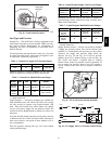
Sensor and Controller Tests
Sensor Alarm Test
The sensor alarm test checks a sensor’s ability to signal an
alarm state. This test requires that you use a field provided
SD--MAG test magnet.
OPERATIONAL TEST HAZARD
Failure to follow this caution may result in personnel
and authority concern.
This test places the duct detector into the alarm state.
Unless part of the test, disconnect all auxiliary
equipment from the controller before performing the
test. If the duct detector is connected to a fire alarm
system, notify the proper authorities before
performing the test.
CAUTION
!
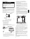
Sensor Alarm Test Procedure
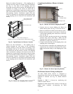
1. Hold the test magnet where indicated on the side of
the sensor housing for seven seconds.
2. Verify that the sensor’s Alarm LED turns on.
3. Reset the sensor by holding the test magnet against
the sensor housing for two seconds.
4. Verify that the sensor’s Alarm LED turns off.
Controller Alarm T
est
The controller alarm test checks the controller’s ability to
initiate and indicate an alarm state.
48TC