


38
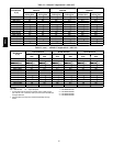
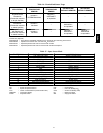
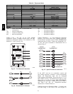
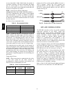
Table 18 – Thermostat Mode
TB1 TERMINAL FIELD CONNECTION INPUT SIGNAL
1 RAT SEN Analog (10k thermistor)
2 G Discrete, 24VAC
3 RAT SEN Analog (10k thermistor)
4 Y1 Discrete, 24VAC
5
6 Y2 Discrete, 24VAC
7 LOOP---PWR A nalog, 24VDC
8 W1 Discrete, 24VAC
9 IA Q --- SE N An alog, 4 --- 20m A
10 W2 Discrete, 24VAC
11 IA Q --- CO M/O AQ --- CO M/ RH --- CO M Analog, 4 --- 20m A
12 CCN + (RED) Digital, 5VDC
13 OAQ --- SE N/R H --- SE N A nalog, 4 --- 20mA
14 CCN Gnd (WHT) Digital, 5VDC
15 AUX OUT (P o wer Exhaust) (Output) Discrete 24VAC
16 CCN --- (BLK) Digital, 5VDC
LEGEND:
CCN --- Carrier Comfort Network (communication bus)
G --- Ther mostat Fa n
IAQ --- Indoor Air Quality (CO
2
)
OAQ --- Outdoor Air Quality (CO
2
)
RAT --- Return Air Temperature
RH --- Relative Humidity
W1 --- Thermostat Heat Stage 1
W2 --- Thermostat Heat Stage 2
Y1 --- Thermostat Cool Stage 1
Y2 --- Thermostat Cool Stage 2
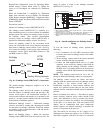
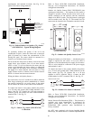
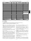
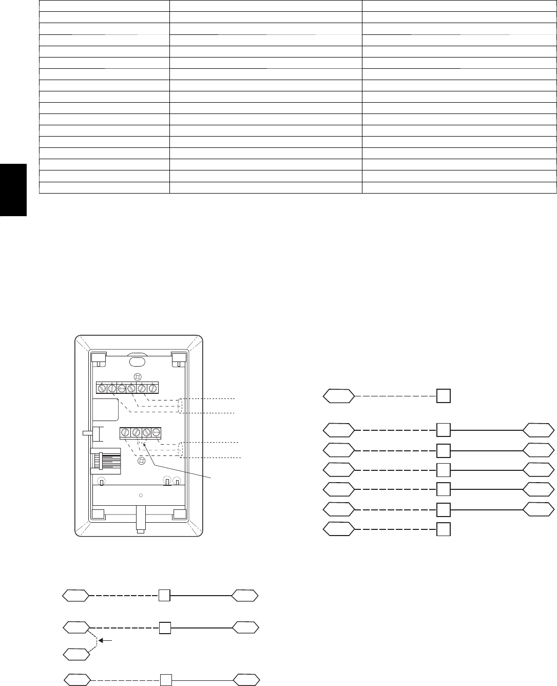
Connect T--56 -- See Fig. 45 for T--56 internal
connections. Install a jumper between SEN and SET
terminals as illustrated. Connect T--56 terminals to TB1
terminals 1, 3 and 5 (see Fig. 46).
2
3
45
61
SW1
SEN
SET
Cool Warm
BRN (GND)
BLU (SPT)
RED(+)
WHT(GND)
BLK(-)
CCN COM
SENSOR WIRING
JUMPER
TERMINALS
AS SHOWN
BLK
(T56)
C08202
Fig. 45 -- T--56 Internal Connections
SEN J6-7
J6-6
1
3
TB1 PL
SEN
SET
Jumper
TB1
PL
J6-5
5
SET
C08213
Fig. 46 -- PremierLink T--56 Sensor
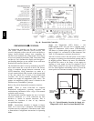
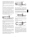
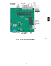
Connect Thermostat — A 7--wire thermostat connection
requires a 24--v power source and a common connection.
Use the R and C terminals on the LCTB’s THERMOSTAT
connection strip for these. Connect the thermostat’s Y1,
Y2, W1, W2 and G terminals to PremierLink TB1 as
shown in Fig. 47.
G J4-12
J4-10
J4-8
Y1
Y2
2
R
R
4
6
J4-6
J4-4
W2
C
8
10
C
SPACE
THERMOSTAT
PL
LCTB
THERMOSTAT
W1
TB1
LCTB
THERMOSTAT
C08119
Fig. 47 -- Space Thermostat Connections
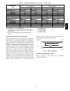
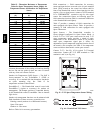
If the 48TC unit has an economizer system and
free--cooling operation is required, a sensor representing
Return Air Temperature must also be connected
(field--supplied and installed). This sensor may be a T--55
Space Sensor (see Fig. 43) installed in the space or in the
return duct, or it may be sensor PNO 33ZCSENSAT,
installed in the return duct. Connect this sensor to TB1--1
and TB1--3 per Fig. 44. Temperature--resistance
characteristic is found in Table 15.
Configure the unit for Thermostat Mode — Connect to the
CCN bus using a CCN service tool and navigate to
48TC