


78
source for a 3V control system, the PremierLink controller
is not required to be on the same CCN bus but it is
recommended. Linkage will be active when it is initiated
from the Linkage thermostat or the 3V Linkage
Coordinator through CCN communications and requires
no configuration. Only one device can be linked to the
PremierLink controller.
Once Linkage is active, the PremierLink controller’s own
SPT, temperature setpoints, and occupancy are ignored
and the controller will use the information provided by the
remote linkage device. The following information will be
received from the remote linked device and can be viewed
in the maintenance display table:
S Supervisory Element
S Supervisory Bus
S Supervisory Block
S Average Occupied Heat Setpoint
S Average Occupied Cool Setpoint
S Average Unoccupied Heat Setpoint
S Average Unoccupied Cool Setpoint
S Average Zone Temp
S Average Occupied Zone Temp
S Occupancy Status
In return, the PremierLink controller will provide its SAT
and operating mode to the linked device.
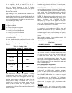
It will convert its operating modes to Linkage modes. See
Table 30.
Table 30 – Linkage Modes
ROOFTOP MODE VALUE LINKAGE MODE
Demand Limit N/A N/A
Heat 3 Heating
Cool or Free Cooling 4 Cooling
IAQ Control N/A N/A
Temp. Compensated
Start H eat
2 Warm ---up
Temp. Compensated
Start Cool
4 Cooling
IAQ Purge 6 Pressurization
Occupied
(Indoor Fan ON)
4 Cooling
Unoccupied Free
Cool
5
Unoccupied Free
Cooling
Fire Shutdown 7 Evac
Factory/Field Test 1 Off
Off 1 Off
The PremierLink controller will generate a Linkage
Communication Failure alarm if a failure occurs for 5
consecutive minutes once a Linkage has previously been
established. It will then revert back to its own SPT,
setpoints and occupancy schedule for control. For this
reason, Carrier strongly recommends that an SPT be
installed in the space on open plenum systems or in the
return air duct of ducted return air systems to provide
continued backup operation. When Linkage
communication is restored, the controller will generate a
return to normal.
For more information on how the PremierLink controller
is used in conjunction with the Carrier 3V control system,
contact your CCN controls representative.
IMPORTANT: The PremierLink controller should not be
used as a linked air source in a ComfortIDt VAV system.
The ComfortID VAV system will NOT function correctly
when applied with a PremierLink controller as the air
source, resulting in poor comfort control and possible
equipment malfunction.
NOTE: The PremierLink controller can be used as an air
source in a 3V Pressure Independent (PI) System (a 3V
Linkage Coordinator with ComfortID PI Zone
Controllers), but it should not be used as an air source
with ComfortID controllers unless a 3V zone controller is
used as the Linkage Coordinator. Contact your Carrier
CCN controls representative for assistance.
Demand Limit — If the demand limit option is enabled,
the control will receive and accept Redline Alert and
Loadshed commands from the CCN loadshed controller.
When a redline alert is received, the control will set the
maximum stage of capacity equal to the stage of capacity
that the unit is operating at when the redline alert was
initiated.
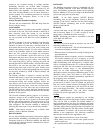
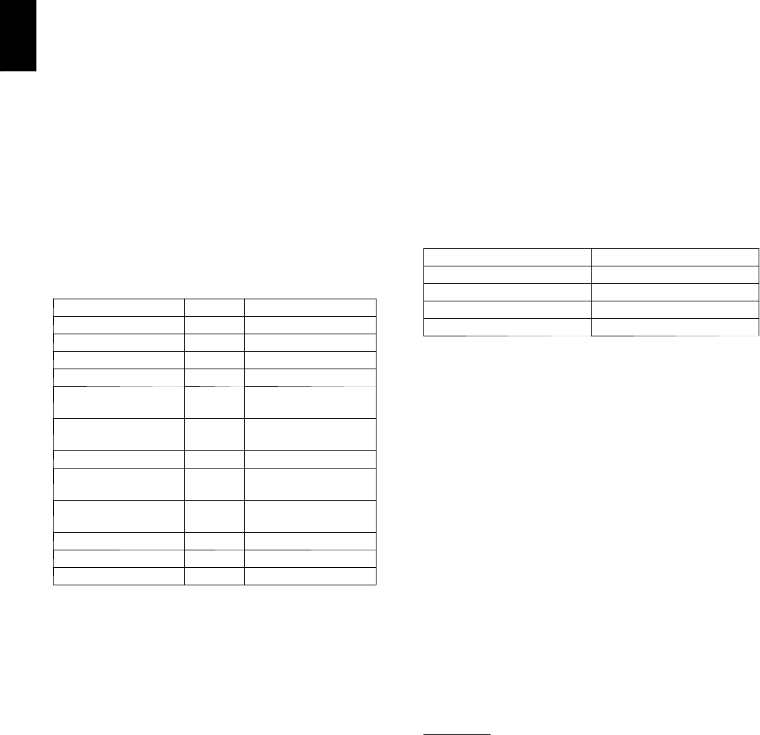
When loadshed command is received the control will
reduce capacity as shown in Table 31.
Table 31 – Loadshed Command — Gas and Electric
Heat Units
CURRENT CAPACITY NEW CAPACITY
CMP1 D X Cooling OFF
CMP1+CMP2 CMP1
HS1 Heat OFF
HS1+HS2 (+HS3) HS1
The controller will have a maximum demand limit timer
of 1 hour that prevents the unit from staying in load shed
or redline alert longer than 1 hour in the event the
controller loses communication with the network load
shed module. Should the maximum demand limit timer
expire prior to receiving the loadshed device command
from CCN, the control will stop demand limit mode and
return to normal operation.
RTU--MP Sequence of Operation
The RTU--MP will control the compressor, economizer
and heating outputs based on its own space temperature
input and setpoints. An optional CO
2
IAQ sensor mounted
in the space can influence the economizer minimum
position. The RTU--MP has its own hardware clock that is
set automatically when the software is installed on the
board. The RTU--MP’s default is to control to occupied
setpoints all the time, until a type of occupancy control is
set. Occupancy types are described in the scheduling
section. The following sections describe the operation for
the functions of the RTU--MP. All point objects that are
referred to in this sequence will be in reference to the
objects as viewed in BACview
6
Handheld.
Scheduling
Scheduling is used to start heating or cooling (become
occupied) based upon a day of week and a time period and
48TC