


27
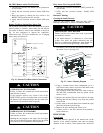
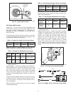
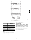
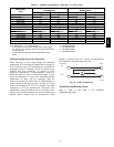
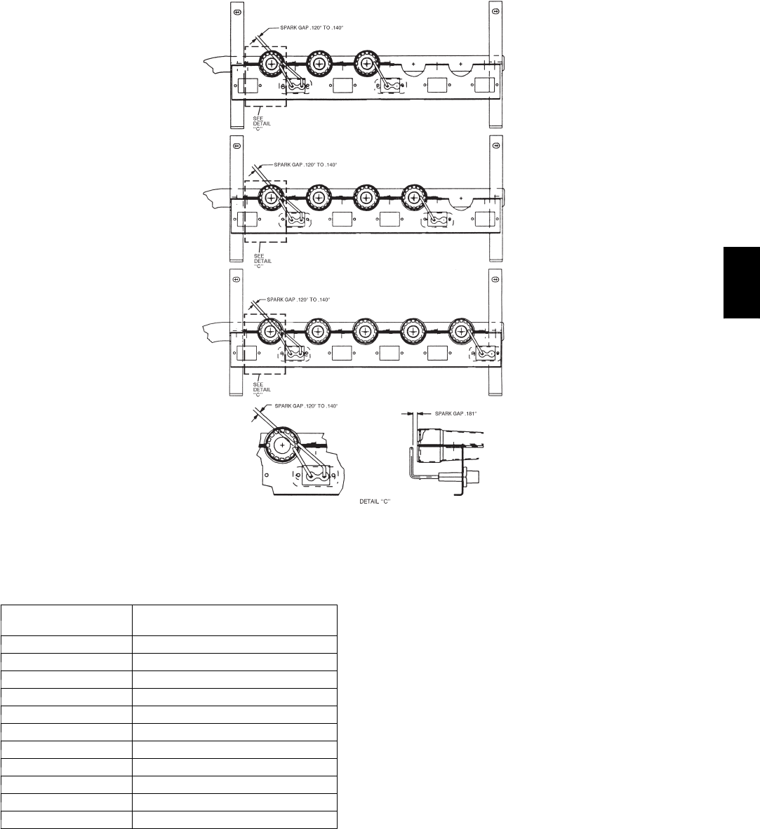
125,000/90,000 BTUH INPUT
180,000/120,000 BTUH INPUT
240,000/180,000 BTUH INPUT
250,000/200,000 BTUH INPUT
C08447
Fig. 36 -- Spark Adjustment (08--12)
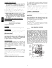
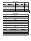
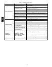
Table 8 – LED Error Code Description*
LED INDICATION
ERROR CODE
DESCRIPTION
ON Normal Operation
OFF Hardware Failure
1Flash{ Evaporator Fan On/O ff Delay Modified
2Flashes Limit Switch Fault
3Flashes Flame Sense Fault
4Flashes 4 Consecutive Limit Switch Faults
5Flashes Ignition Lockout Fault
6Flashes I nduced---Draft Motor Fault
7Flashes Rollout Switch Fault
8Flashes Internal Control Fault
9Flashes Software Lockout
LEGEND
LED --- Lig ht Emitting Diode
* A 3---second pause exists between LED error code flashes. If.
more than one error code exists, all applicable codes will b e
displayed in numerical sequence.
{ Indicates a code that is not an error. The unit will continue to
operate when this code is displayed.
IMPORTANT: Refer to Troubleshooting Table 13 and
Table 14 for additional information.
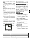
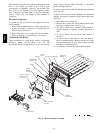
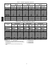
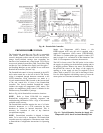
Orifice Replacement
This unit uses orifice type LH32RFnnn (where nnn
indicates orifice reference size). When replacing unit
orifices, order the necessary parts via Carrier RCD. See
Table 10 for available orifice sizes. See Table 11 and
Table 12 for orifice sizes for Natural Gas and LP fuel
usage at various elevations above sea level.
Check that each replacement orifice is tight at its threads
into the manifold pipe and that orifice projection does not
exceed maximum value. See Fig. 32.
48TC