


48
Alarm state is reset when the smoke detector alarm
condition is cleared and reset at the smoke detector in the
unit.
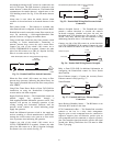
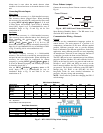
Connecting Discrete Inputs
Filter Status
The filter status accessory is a field--installed accessory.
This accessory detects plugged filters. When installing
this accessory, the unit must be configured for filter status
by setting MENU
→
Config
→
Inputs
→
input3,5,8,or9
to Filter Status and normally open (N/O) or normally
closed (N/C). Input 8 or 9 is recommended for easy of
installation. Refer to Fig. 59 and Fig. 60 for wire
terminations at J5.
Fan
Status
The fan status accessory is a field--installed accessory.
This accessory detects when the indoor fan is blowing air.
When installing this accessory, the unit must be
configured for fan status by setting
MENU
→
Config
→
Inputs
→
input3,5,8,or9to Fan
Status and normally open (N/O) or normally closed (N/C).
Input 8 or 9 is recommended for easy of installation. Refer
to Fig. 59 and Fig. 60 for wire terminations at J5.
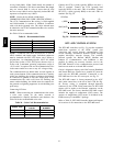
Remote
Occupancy
The remote occupancy accessory is a field--installed
accessory. This accessory overrides the unoccupied mode
and puts the unit in occupied mode. When installing this
accessory, the unit must be configured for remote
occupancy by setting MENU
→
Config
→
Inputs
→
input 3,
5, 8, or 9 to Remote Occupancy and normally open (N/O)
or normally closed (N/C).
Also set MENU
→
Schedules
→
occupancy source to DI
on/off. Input 8 or 9 is recommended for easy of
installation. Refer to Fig. 59 and Table 21 for wire
terminations at J5.
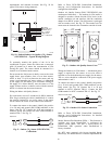
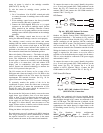
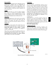
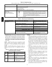
Power Exhaust (output)
Connect the accessory Power Exhaust contactor coil(s) per
Fig. 66.
Power Exhaust
J11-3
C
THERMOSTAT
PEC
TAN
GRA
LCTB
C08464
Fig. 66 -- RTU--MP Power Exhaust Connections
Space Relative Humidity Sensor -- The RH sensor is not
used with 48TC models at this time.
Communication Wiring -- Protocols
General
Protocols are the communication languages spoken by
control devices. The main purpose of a protocol is to
communicate information in the most efficient method
possible. Different protocols exist to provide different
kinds of information for different applications. In the BAS
application, many different protocols are used, depending
on manufacturer. Protocols do not change the function of
a controller; just make the front end user different.
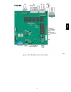
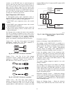
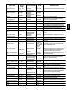
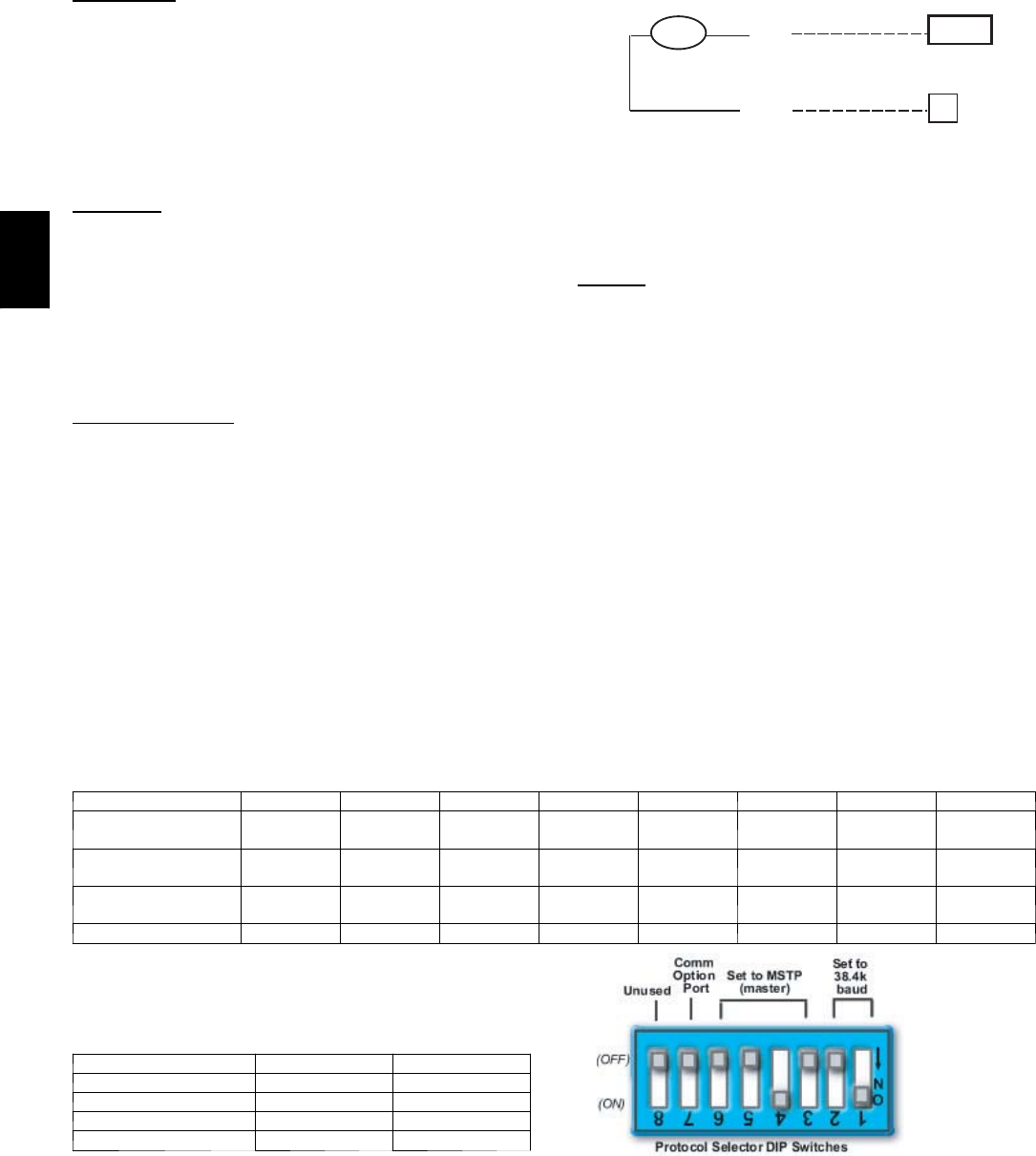
The RTU--MP can be set to communicate on four different
protocols: BACnet, Modbus, N2, and LonWorks. Switch 3
(SW3) on the board is used to set protocol and baud rate.
Switches 1 and 2 (SW1 and SW2) are used to set the
board’s network address. See Fig 67 for the switch setting
per protocol. The 3rd party connection to the RTU--MP is
through plug J19. Refer to the RTU --MP 3rd Party
Integration Guide for more detailed information on
protocols, 3rd party wiring, and networking.
NOTE: Power must be cycled after changing the SW1--3
switch settings.
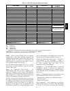
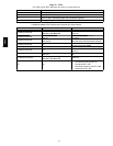
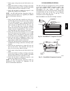
SW3 Protocol Selection
PROTOCOL DS8 DS7 DS6 DS5 DS4 DS3 DS2 DS1
BACnet MS/TP
(Master)
Unused OFF OFF OFF ON OFF Select Baud Select Baud
Modbus
(Slave)
Unused OFF OFF ON ON OFF Select Baud Select Baud
N2
(Slave)
Unused OFF OFF OFF ON ON OFF OFF
LonWorks Unused ON ON OFF ON OFF OFF OFF
NOTE:
DS = Dip Switch
BACnet MS/TP SW3 example shown
Baud Rate Selections
BAUD RATE DS2 DS1
9600 OFF OFF
19,200 ON OFF
38,400 OFF ON
76,800 ON ON
C07166
Fig. 67 -- RTU--MP SW3 Dip Switch Settings
48TC