


26
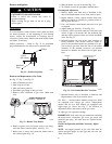
1. Remove manifold pressure tap plug from manifold
and connect pressure gauge or manometer. (See Fig.
33.)
2. Turn on electrical supply.
3. Turn on unit main gas valve.
4. Set room thermostat to call for heat. If unit has two--
stage gas valve, verify high--stage heat operation be-
fore attempting to adjust manifold pressure.
5. When main burners ignite, check all fittings, mani-
fold, and orifices for leaks.
6. Adjust high--stage pressure to specified setting by
turning the plastic adjustment screw clockwise to in-
crease pressure, counter--clockwise to decrease pres-
sure.
7. For Two--Stage Gas Valves set room thermostat to
call for low--stage heat. Adjust low--stage pressure to
specified setting.
8. Replace regulator cover screw(s) when finished.
9. With burner access panel removed, observe unit heat-
ing operation in both high stage and low stage opera-
tion if so equipped. Observe burner flames to see if
they are blue in appearance, and that the flames are
approximately the same for each burner.
10. Turn off unit, remove pressure manometer and re-
place the 1/8 in. pipe fitting on the gas manifold. (See
Fig. 32.)
Limit
Switch
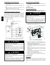
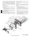
Remove blower access panel. Limit switch is located on
the fan deck. See Fig. 28.
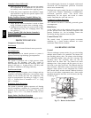
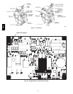
Burner Ignition
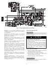
Unit is equipped with a direct spark ignition 100% lockout
system. Integrated Gas Unit Controller (IGC) is located in
the control box. See Fig. 34. The IGC contains a
self--diagnostic LED (light--emitting diode). A single LED
(see Fig. 38) on the IGC provides a visual display of
operational or sequential problems when the power supply
is uninterrupted. When a break in power occurs, the IGC
will be reset (resulting in a loss of fault history) and the
indoor (evaporator) fan ON/OFF times will be reset. The
LED error code can be observed through the viewport.
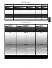
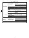
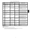
During servicing refer to the label on the control box
cover or Table 8 for an explanation of LED error code
descriptions.
If lockout occurs, unit may be reset by interrupting power
supply to unit for at least 5 seconds.
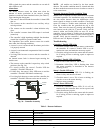
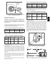
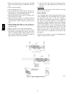
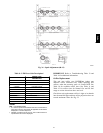
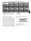
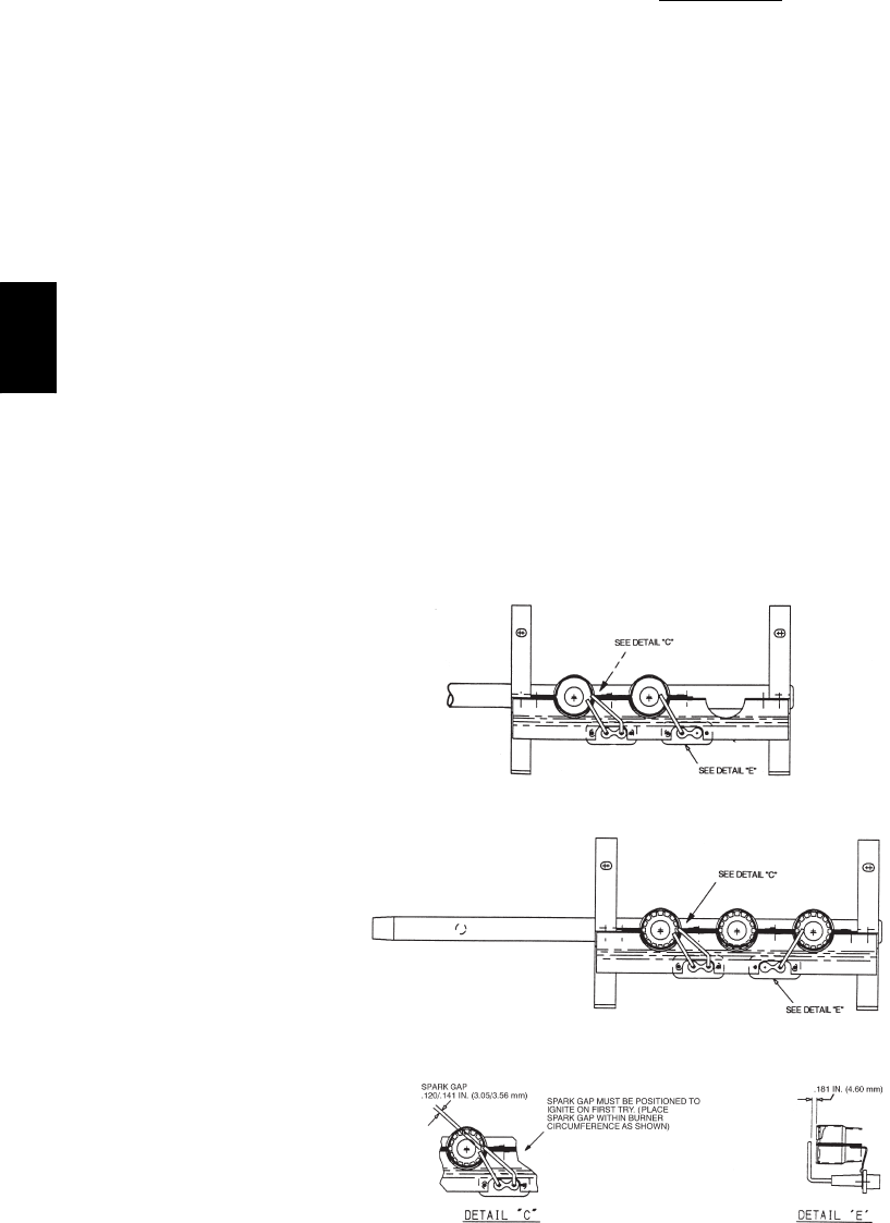
72,000 BTUH INPUT AND 60,000 BTUH INPUT
115,000 BTUH INPUT,
150,000 BTUH INPUT,
90,000BTUH INPUT AND
120,000 BTUH INPUT
LOW HEAT
MEDIUM AND HIGH HEAT
C06154
Fig. 35 -- Spark Adjustment (04--07)
48TC