


Viper Service Manual
© 2010, IMI Cornelius Inc. - 9 - Publication Number: 621360041TBSER
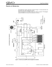
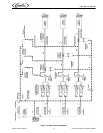
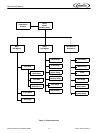
An overall schematic of the three delivery systems contained in the unit are
shown in Figure 5. The CO
2 system is on top, the water system is in the middle
and the syrup system is at the bottom of the diagram. The CO
2 system interacts
with both the water and syrup systems. It provides pressure and carbonation for
the syrup/water product mix.
CO2 System
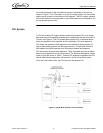
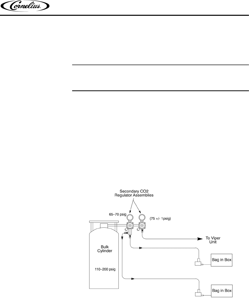
A CO2 tank or bulk CO2 supply delivers carbon dioxide gas (CO2) to an adjust-
able secondary CO
2 regulator assembly that is attached to the tank as shown in
Figure 3 and Figure 4. The CO
2 system also supplies CO2 to the water boost
pump, the expansion tank regulator and the secondary CO
2 tank regulators.
CO
2 enters the expansion tank regulator and is reduced to approximately 30
psig to feed holding pressure on the expansion tank. This provides a force to
work against the barrel pressure when the product freezes and expands.
CO
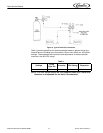
2 also enters the secondary regulators. These regulators are used to adjust
barrel overrun/expansion for various products. The pressure settings for various
types of syrup are shown in Table 1. Overrun CO
2 pressure is applied to the CO2
control solenoids through preset orifices and on to the in-line check valves.
From the in-line check valve, the CO
2 flows into the product line.
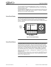
Figure 3. Typical Bulk Cylinder CO2 Connection