


108
6 WIRING
6.8 Examples of Wiring for Various Uses
Seven Segment with Latch
For the instructions, refer to MELSEC iQ-F FX5 Programming Manual (Instructions, Standard Functions/Function Blocks).
When SEGL instructions are used
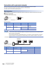
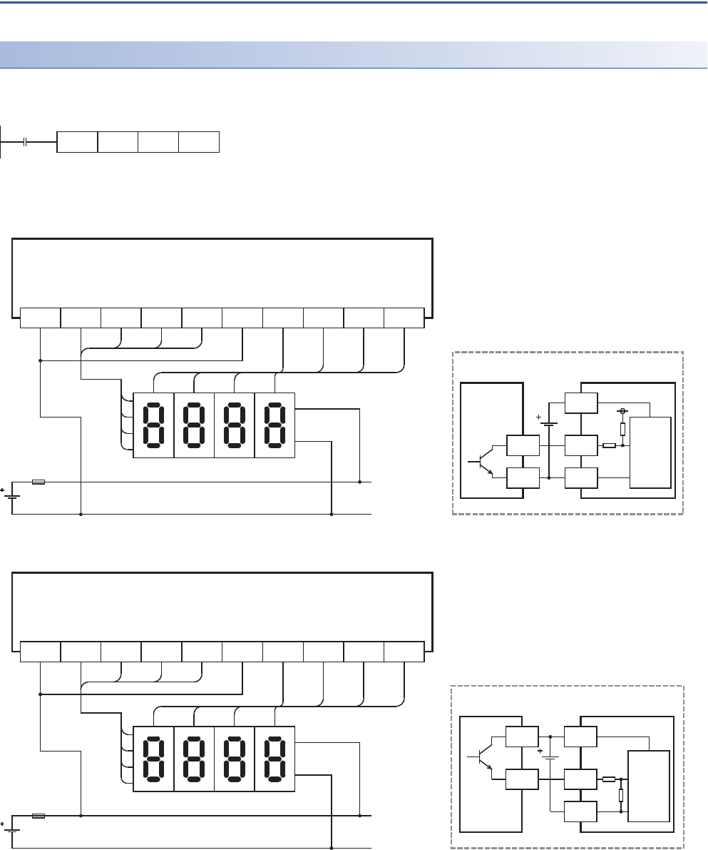
Examples of wiring for displaying the current value of D100 on the 4-digit 7-segment display are given below.
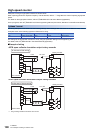
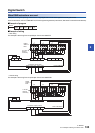
■Example of program
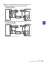
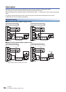
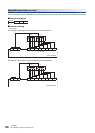
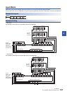
■Example of wiring
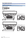
• Sink wiring
The example is the wiring for the input/output of the FX5U-32MT/ES.
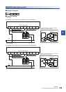
• Source wiring
The example is the wiring for the input/output of the FX5U-32MT/ESS.
*1 Use a 7-segment display with a latch and a built-in BCD decoder.
SEGL
SM400
D100 Y010 K1
10
3
10
2
10
1
10
0
124
8
10
3
10
2
10
1
10
0
1
2
4
Y010 Y011 Y012 Y013 Y014COM3 Y015 Y016 Y017
8
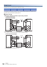
Transistor output (sink)
*1
COM2
FX5U-32MT/ES
Signal
-
Internal
circuit
Seven Segment
with Latch
+
Y
COM1
PLC
7-segment display to be used for sink wiring
(in the case of transistor output)
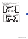
Fuse
Signal
-
Internal
circuit
Seven Segment
with Latch
+
Y
PLC
+V0
7-segment display to be used for source wiring
(in the case of transistor output)
10
3
10
2
10
1
10
0
124
8
10
3
10
2
10
1
10
0
1
2
4
Y010 Y011 Y012 Y013 Y014+V3 Y015 Y016 Y017
8
Transistor output (source)
*1
+V2
FX5U-32MT/ESS
Fuse