


5 INSTALLATION
5.4 Procedures for Installing Directly (with M4 Screws)
69
5
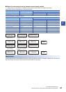
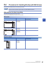
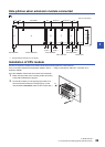
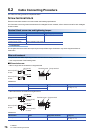
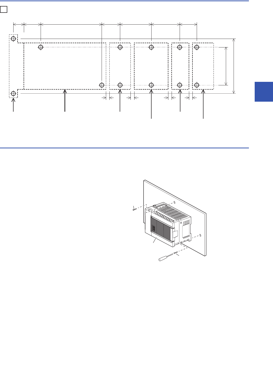
Hole pitches when extension module connected
Ex.
*1 The gap between products is 2 mm (0.08").
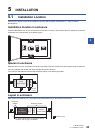
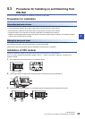
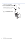
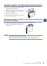
Installation of CPU module
Connect the expansion adapter to the CPU module before mounting the PLC in the enclosure.
For the connection method of the expansion adapter, refer to Page 72 Connection method B - connection of an
expansion adapter.
The FX5U-32M is used as the CPU module in this example.
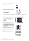
1. Make mounting holes on the mounting surface according
to the external dimensions diagram.
2. Fit the CPU module (A in the right figure) to holes, and
secure it with M4 screws (B in the right figure). (In the
case of FX5U-64M/80M, there are four screw holes.)
A
C
D
F H
98 (3.86")
80 (3.15")
Unit: mm (inches)
2
*1
(0.08")
2
*1
(0.08")
2
*1
(0.08")
2
*1
(0.08")
FX5-232ADP FX5U-32MT/ES FX5-16EX/ES
FX5-1PSU-5V
FX5-CNV-BUS
FX3U-1PG
123 (4.85") 27
(1.07")
38 (1.5") 44 (1.74")
15.1
(0.6")
14
(0.56")
22
(0.87")
B
B
A