


2 SPECIFICATIONS
2.1 Generic Specifications
17
2
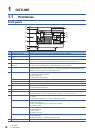
2 SPECIFICATIONS
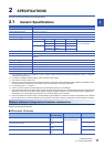
The CPU module specifications are explained below.
2.1 Generic Specifications
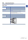
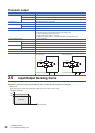
*1 The simultaneous ON ratio of available PLC inputs or outputs changes with respect to the ambient temperature, refer to Page 22
Input/Output Derating Curve.
*2 For details on Intelligent function modules, refer to manuals of each product.
*3 The criterion is shown in IEC61131-2.
*4 When the system has equipment which specification values are lower than above mentioned vibration resistance specification values,
the vibration resistance specification of the whole system is corresponding to the lower specification.
*5 For grounding, refer to Page 78
*6 The PLC cannot be used at a pressure higher than the atmospheric pressure to avoid damage.
*7 This indicates the section of the power supply to which the equipment is assumed to be connected between the public electrical power
distribution network and the machinery within premises. Category applies to equipment for which electrical power is supplied from
fixed facilities. The surge voltage withstand level for up to the rated voltage of 300 V is 2500 V.
*8 This index indicates the degree to which conductive material is generated in the environment in which the equipment is used. Pollution
level 2 is when only non-conductive pollution occurs. Temporary conductivity caused by condensation must be expected occasionally.
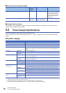
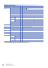
Dielectric withstand voltage test and insulation resistance test
Perform dielectric withstand voltage test and insulation resistance test at the following voltages between each terminal and
the CPU module ground terminal.
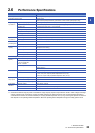
■ CPU module, I/O module
Item Specifications
Operating ambient temperature
*1
0 to 55 (32 to 131 )
*2
Storage ambient temperature -25 to 75 (-13 to 167 )
Operating ambient humidity 5 to 95%RH, non-condensation
Storage ambient humidity 5 to 95%RH, non-condensation
Vibration resistance
*3*4
Frequency Acceleration Half amplitude Sweep count
Installed on DIN rail 5 to 8.4 Hz 1.75 mm 10 times each in X, Y, Z directions
(80 min in each direction)
8.4 to 150 Hz 4.9 m/
Direct installing 5 to 8.4 Hz 3.5 mm
8.4 to 150 Hz 9.8 m/
Shock resistance
*3
147 m/, Action time: 11 ms, 3 times by half-sine pulse in each direction X, Y, and Z
Noise durability By noise simulator at noise voltage of 1000 Vp-p, noise width of 1 s and period of 30 to 100 Hz
Grounding Class D grounding (grounding resistance: 100 or less) <Common grounding with a heavy electrical system is not
allowed.>
*5
Working atmosphere Free from corrosive or flammable gas and excessive conductive dust
Operating altitude
*6
0 to 2000 m
Installation location Inside a control panel
Overvoltage category
*7
or less
Pollution degree
*8
2 or less
Equipment class Class 2
Between terminals Dielectric
withstand voltage
Insulation resistance Remarks
Between power supply terminal (AC power supply) and ground terminal 1.5 kV AC for one
minute
10 M or higher by 500 V DC
insulation resistance tester
Between 24 V DC service power supply connected to input terminal (24
V DC) and ground terminal
500 V AC for one
minute
Between output terminal (relay) and ground terminal 1.5 kV AC for one
minute
Between output terminal (transistor) and ground terminal 500 V AC for one
minute