


6 WIRING
6.6 Output Wiring
93
6
■Response time
Time taken from when the photocoupler of the module is driven (or shut off) to when the transistor is turned on (or off) differs
depending on the output terminal used. For specifications of each module, refer to the following.
For output specifications of the CPU module, refer to Page 21 Output Specifications.
For output specifications of the I/O modules, refer to Page 136 Output specifications.
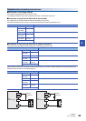
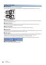
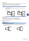
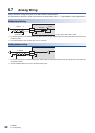
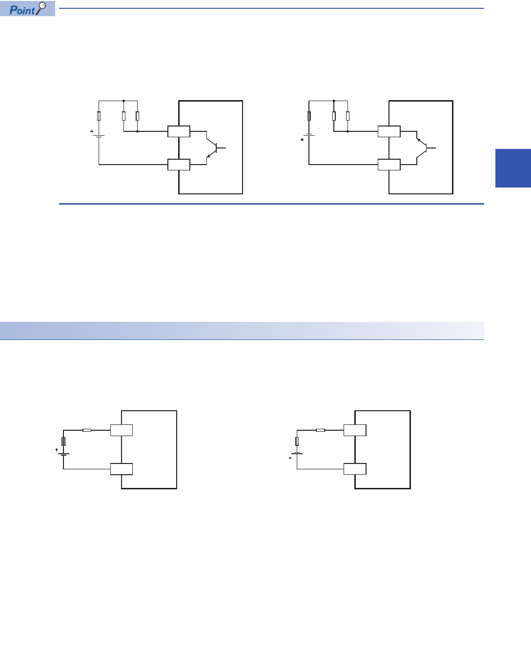
The transistor OFF time is longer under lighter loads. For example, under a load of 24 V DC 40 mA, the
response time is approx. 0.3 ms.
When response performance is required under light loads, provide a dummy resistor as shown below to
increase the load current.
■Output current
Maximum load differs for each module. For specifications of each module, refer to the following.
For output specifications of the CPU module, refer to Page 21 Output Specifications.
For output specifications of the I/O modules, refer to Page 136 Output specifications.
When driving a semiconductor device, carefully check the input voltage characteristics of the device.
■Open circuit leakage current
0.1 mA or less
Wiring precautions
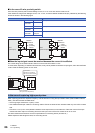
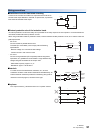
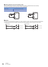
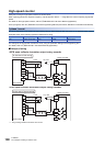
■Protection circuit for load short-circuiting
A short-circuit at a load connected to an output terminal could cause burnout at the output device or the PCB.
To prevent this, a protection fuse should be inserted at the output. Use a load power supply capacity that is at least 2
times larger than the load current.
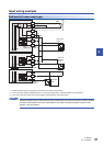
PLCs
Y
COM0
LoadFuse
• Sink output type • Source output type
PLCs
Y
+V0
LoadFuse
Dummy
resistor
Dummy
resistor
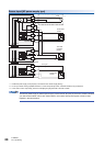
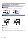
PLCs
Y
COM0
Load
Fuse
Sink output type
Y
+V0
PLCs
Load
Fuse
Source output type