


82
6 WIRING
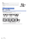
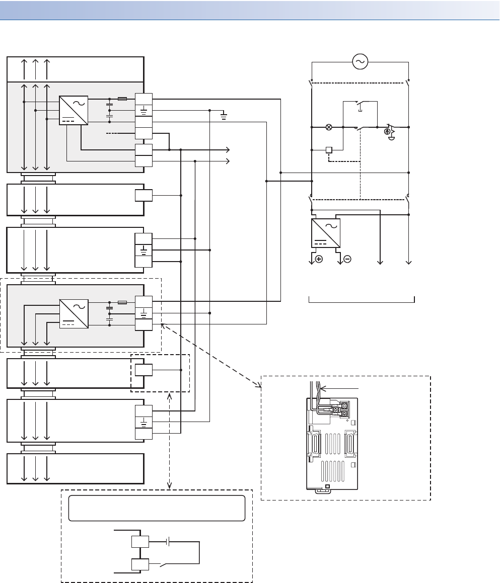
6.4 Power Supply Wiring
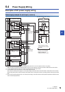
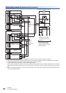
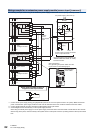
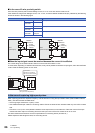
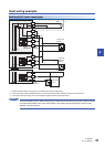
Wiring example for an extension power supply module (source input [+common])
The following example shows wiring for an extension power supply module when source input [+common] is used.
*1 Connect the AC power supply to the [L] and [N] terminals (common for 100 V AC system and 200 V AC system). Make sure that the
power of the extension power supply module is turned on at the same time as the CPU module or earlier than the CPU module.
*2 Connect the [0V] terminal of the CPU module to the [S/S] terminal of the input module.
*3 Some intelligent function modules may not have power supply terminals.
When using an external power supply, turn on the power supply at the same time as the CPU module or earlier than the CPU module.
When turning off the power, confirm the safety of the system and turn off the power of the PLC (including extension devices) at the same
time.
AC power supply (100 to 240 V)
S/S
L
N
0V
Expansion adapter
PL
Power ON
MC
MC
MC MC
24V
CPU module
Input module
S/S
Class D grounding
DC AC
*1
*2
Breaker
24-
24+
*3
FX5
intelligent module
L
N
S/S
*1
*3
Extension power supply module
FX5
intelligent module
Input module
Output module
24-
24+
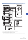
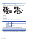
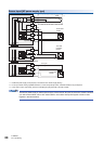
Wiring precaution:
24 V DC
service
power supply
output
Emergency
stop
Power supply for loads connected
to PLC output terminals
As for emergency stop operation, see
"DESIGN PRECAUTIONS" at "Safety
Precautions" field.
Run grounding and power cables from the
top as shown in the following figure.
DC power
supply
Grounding and
power cables
5 V 0 V 24 V
5 V 0 V 24 V
5 V 0 V 24 V
5 V 0 V 24 V
5 V 0 V 24 V
5 V 0 V 24 V
5 V 0 V 24 V
5 V 0 V 24 V
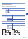
*2
When external power supply is
supplied to the input circuit
X
S/S