


6 WIRING
6.6 Output Wiring
91
6
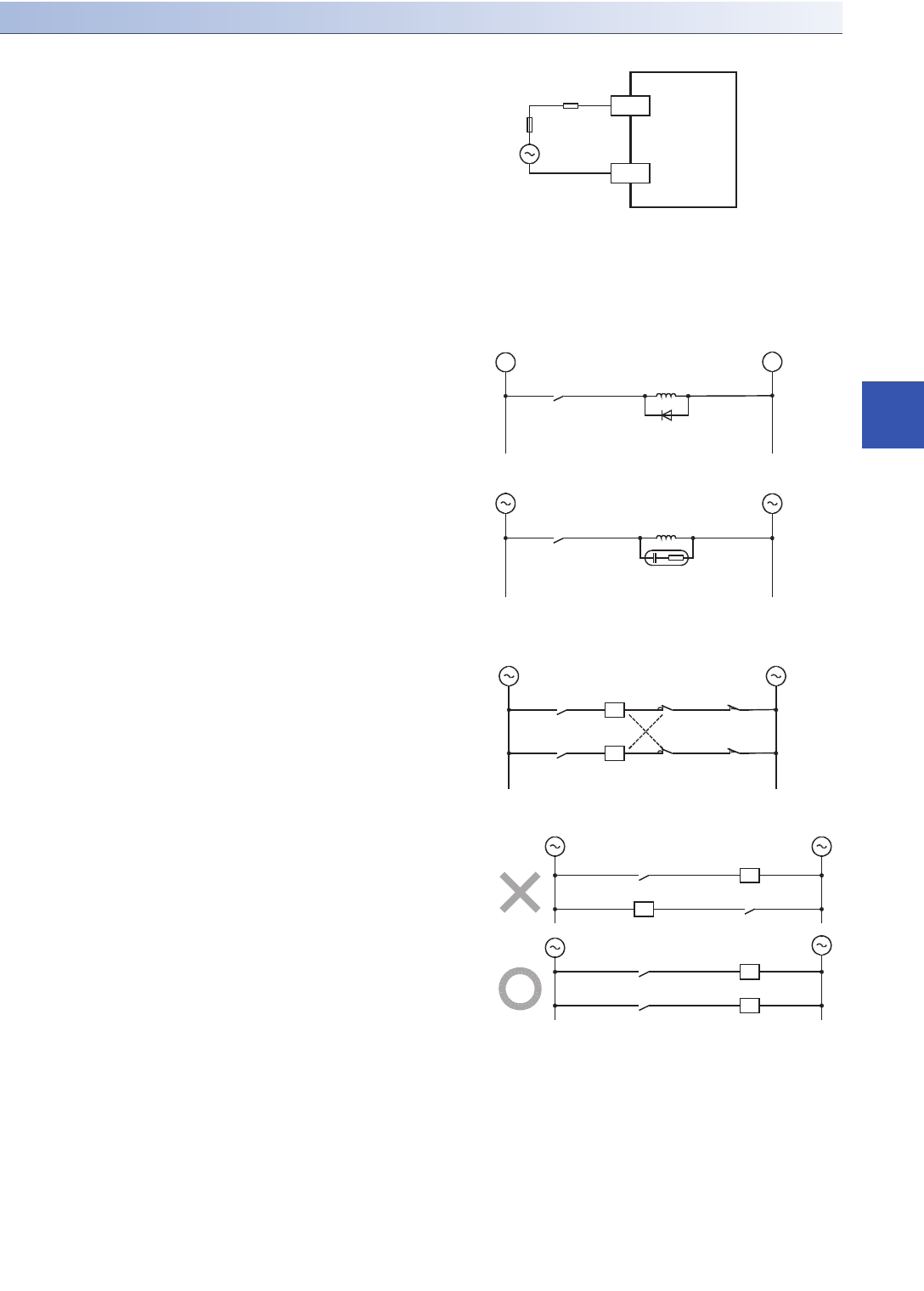
Wiring precautions
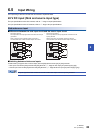
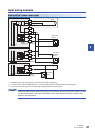
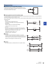
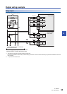
■Protection circuit for load short-circuiting
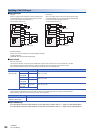
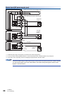
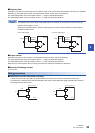
■Contact protection circuit for inductive loads
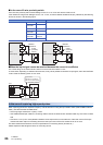
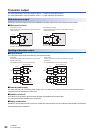
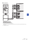
■Interlock
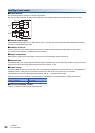
■In-phase
A short-circuit at a load connected to an output terminal could cause
burnout at the output element or the PCB. To prevent this, a protection
fuse should be inserted at the output.
An internal protection circuit for the relays is not provided for the relay output circuit in this product. It is recommended to
use inductive loads with built-in protection circuits.
When using loads without built-in protection circuits, insert an external contact protection circuit, etc. to reduce noise and
extend product life.
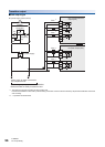
•
DC circuit
Connect a diode in parallel with the load.
The diode (for commutation) must comply with the following
specifications.
Reverse voltage: 5 to 10 times the load voltage
Forward current: Load current or more
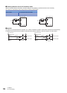
•
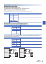
AC circuit
Connect a surge absorber (CR composite parts like surge killer,
spark killer, etc.) parallel to the load. Select a surge absorber with
voltage rating that is suitable for the output used.
Electrostatic capacity: Approx. 0.1 F
Resistance: Approx. 100 to 200
For loads such as forward/reverse contactors, etc., where a
hazardous condition could result if switched ON simultaneously, an
external interlock should be provided for interlocking along with an
interlock in the PLC program, as shown to the right.
PLC output contacts (*) should be used in an "in-phase" manner.
PLCs
COM0
Load
Fuse
Y0
+
-
Inductive load
Diode (for commutation)
PLC output contact
Inductive load
PLC output contact
Surge
absorber
Interlock
PLC output
contact
PLC output
contact
Limit of forward
rotation
Limit of reverse
rotation
Forward
rotation
Reverse
rotation
*
*
*
*