


110
7 OPERATION ADJUSTMENT
7.1 Preparation for Operation
7 OPERATION ADJUSTMENT
7.1 Preparation for Operation
Preliminary inspection
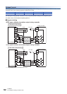
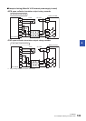
Incorrect connection of the power supply terminal, contact of the DC input wire and power supply wire, or short-circuiting of
output wires may result in serious damage.
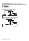
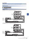
Before applying power, check that the power supply and ground terminals are connected correctly and input/output devices
are wired properly.
Dielectric withstand voltage test and insulation resistance test
The dielectric withstand voltage and insulation resistance test of the PLC should be measured in accordance with the
following procedure.
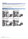
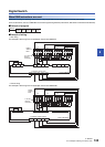
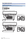
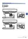
1. Remove all input/output wires and power supply wires from the PLC.
2. Connect a crossing wire to each of the PLC terminals (power supply terminal, input terminals and output terminals)
except the ground terminal. For the dielectric withstand voltage test of each terminal, refer to the generic specifications
for the product (refer to Page 17 Generic Specifications).
3. Measure the dielectric withstand voltage and insulation resistance between each terminal and the ground terminal.
• Dielectric withstand voltage 1.5 kV AC or 500 V AC for 1 min (The terminals vary in dielectric withstand voltage.)
• Insulation resistance 10 M or higher by 500 V DC insulation resistance tester