92
6 WIRING
6.6 Output Wiring
Transistor output
For output specifications of the CPU module, refer to Page 21 Output Specifications.
For output specifications of the I/O modules, refer to Page 136 Output specifications.
Sink and source output
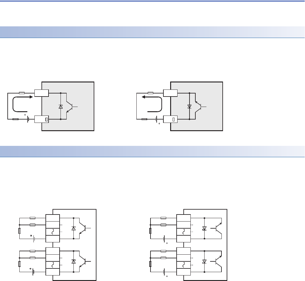
Sink output and source output products are available for transistor outputs of the CPU module and I/O modules.
■Differences in circuit
Handling of transistor output
■Output terminal
4 or 8 transistor output points are covered by one common terminal.
■External power supply
For driving the load, use a smoothing power supply of 5 to 30 V DC that can output current two or more times the current
rating of the fuse connected to the load circuit.
■Insulation of circuit
The internal circuit of the PLC and the output transistor are insulated with a photocoupler.
The common blocks are separated from one another.
■Display of operation
Operation indicator LEDs are built into the CPU module and output modules, and turn ON when photocouplers are activated,
and the transistors are switched on.
• Sink output [-common] • Source output [+common]
Output to make load current flow into the output (Y) terminal is
called sink output.
Output to make load current flow out of the output (Y) terminal
is called source output.
• Sink output • Source output
Connect each COM (number) terminal to the minus side of
the load power supply.
The COM terminals are not connected internally.
Connect +V (number) terminal to the plus side of the load
power supply.
The +V terminals are not connected internally.
Load
Y
Fuse
DC power supply
A number is entered in the of [COM].
COM
Load
Y
Fuse
DC power supply
A number is entered in the of [+V].
+V
PLCs
Load
Fuse
Y0
COM0
Load
Fuse
COM1
Sink output type
Y1
Y4
Y5
DC power
supply
DC power
supply
PLCs
Load
Fuse
+V0
Load
Fuse
+V1
Source output type
Y0
Y1
Y4
Y5
DC power
supply
DC power
supply


