5 INSTALLATION
5.1 Installation Location
63
5
5 INSTALLATION
5.1 Installation Location
Use the PLC under the environmental conditions complying with the generic specifications (Page 17 Generic
Specifications).
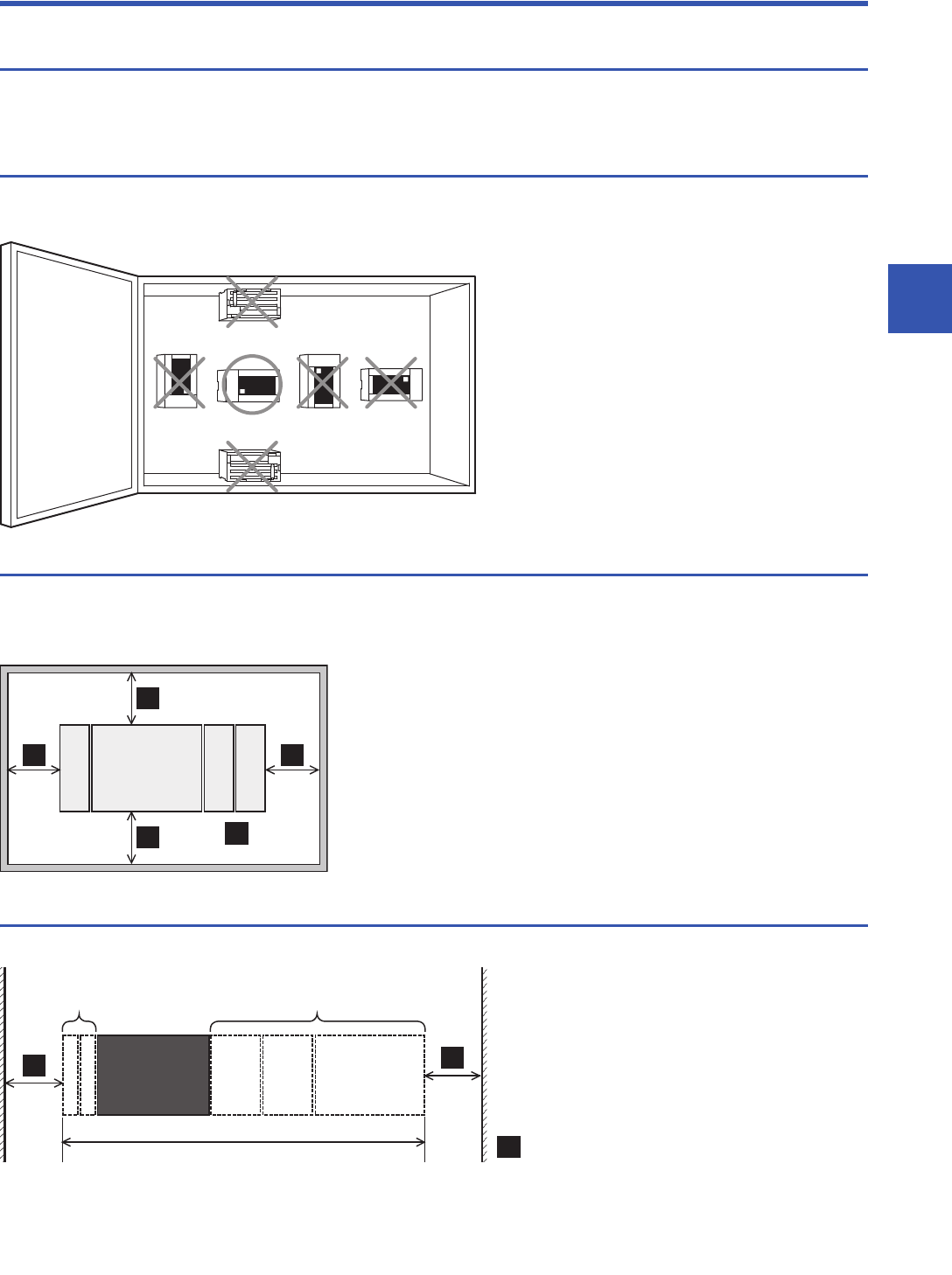
Installation location in enclosure
To prevent temperature rise, do not mount the PLC on the floor or ceiling, or in the vertical direction. Always mount the PLC
horizontally on the wall as shown in the following figure.
Spaces in enclosure
Extension devices can be connected on the left and right sides of the CPU module of the PLC. Keep a space of at least 50
mm (1.97") between the module main body and other devices and structure.
If you intend to add extension devices, keep necessary spaces on the left and right sides.
Layout in enclosure
Keep a space of at least 50 mm (1.97") between the module main body or other devices and structure.
FX5-16EX
FX5-232ADP
FX5-16EYT
A
A
≥50 mm
(1.97")
A
A
A
FX5U
CPU module
Extension module
A
≥50 mm (1.97")A
A
FX5U
CPU module
Intelligent
function module
For product dimensions or manual for various
products, refer to App 3 I/O Module.
Expansion
adapter
Output
module
Input
module


