6 WIRING
6.5 Input Wiring
85
6
Precautions for connecting input devices
■In the case of no-voltage contact
Use input devices appropriate for low electric current.
If no-voltage contacts for high current (switches) are used, contact failure may occur.
■In the case of input device with built-in series diode
The voltage drop of the series diode should be the following value or less.
Also make sure that the input current is over the input-sensing level while the switches are on.
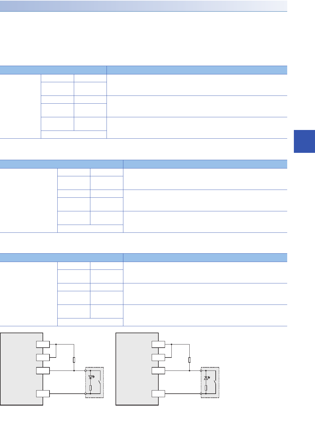
■In the case of input device with built-in parallel resistance
Use a device having a parallel resistance Rp (k) of the following value or more.
If the resistance is less than the above parallel resistance Rp (k), connect a bleeder resistance Rb (k) obtained by the
following formula as shown in the following figure.
Item Specifications
Voltage drop FX5U-32M X000 to X005 3.9 V
FX5U-64M,
FX5U-80M
X000 to X007
FX5U-32M X006 to X017 4.1 V
FX5U-64M,
FX5U-80M
X010 to X017
FX5U-64M,
FX5U-80M
X020 and
subsequent
2.4 V
I/O module
Item Specifications
Parallel resistance Rp (k) FX5U-32M X000 to X005 14
FX5U-64M,
FX5U-80M
X000 to X007
FX5U-32M X006 to X017 15
FX5U-64M,
FX5U-80M
X010 to X017
FX5U-64M,
FX5U-80M
X020 and
subsequent
13
I/O module
Item Specifications
Bleeder resistance Rb (k)FX5U-32M X000 to X005 5 Rp / (14-Rp) or less
FX5U-64M,
FX5U-80M
X000 to X007
FX5U-32M X006 to X017 4 Rp / (15-Rp) or less
FX5U-64M,
FX5U-80M
X010 to X017
FX5U-64M,
FX5U-80M
X020 and
subsequent
6 Rp / (13-Rp) or less
I/O module
X
24V
Rp
Rb
X
0V
Rp
Rb
24V
S/S S/S
0V
PLC
(sink input)
PLC
(source input)
Bleeder
resistance
Bleeder
resistance


