


APPENDIX
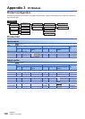
Appendix 3 I/O Module
139
A
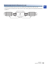
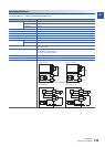
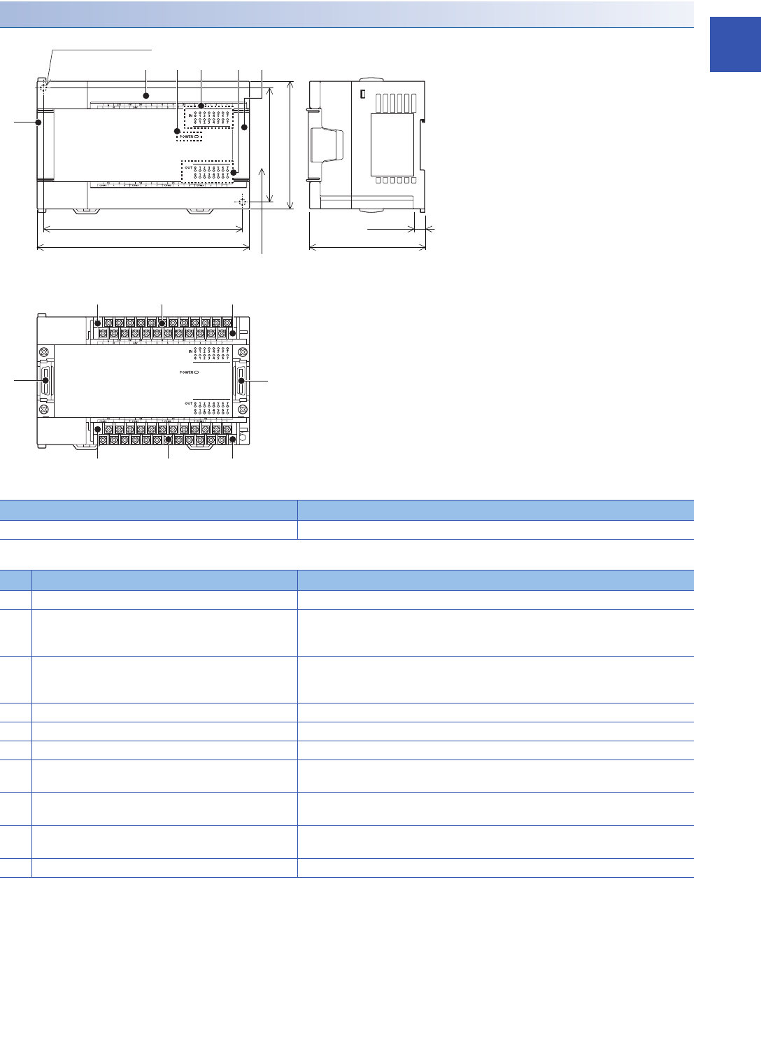
Powered input/output module
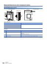
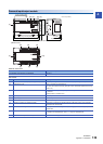
External dimensions
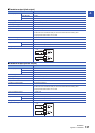
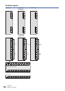
Part names
Model W: mm (inches)
FX5-32ER/ES, FX5-32ET/ES, FX5-32ET/ESS 150 (5.91")
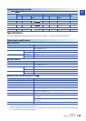
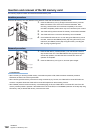
No. Name Description
[1] Extension connector cover (for preceding module) Cover for protecting the extension connector cover (for preceding module).
[2] Terminal block cover Cover for protecting the terminal block.
The cover can be opened for wiring. Keep the covers closed while equipment is running
(power is on).
[3] POWER LED Indicates whether the powered input/output module is powered or not.
Lit: Powered
Off: Not powered or hardware error
[4] Input display LED Lit when input is on.
[5] Output display LED Lit when output is on.
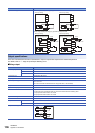
[6] Extension connector cover (for next module) Cover for protecting the extension connector cover (for next module).
[7] Extension connector (for preceding module) Connecter for connecting the supplied extension cable that connects to the preceding
module (the CPU module side).
[8] Terminal block mounting screws Gradually loosen the left and right screws (alternatingly) to remove the upper part of the
terminal block.
[9] Terminal Terminals for power, input, and output.
For details on the terminal layout, refer to Page 140 Terminal layout.
[10] Extension connector (for next module) Connector for connecting the extension cable of an extension module.
140 (5.52")
(mounting hole pitch)
(mounting hole pitch)
80
(3.15")
90
(3.55")
W83
(3.27")
8
(0.32")
2-
4.5 mounting holes
[Without cover]
Unit: mm (inches)
[10]
[1]
[7]
[2]
[8] [9] [8]
[8] [9] [8]
[4] [5] [6][3]