


90
6 WIRING
6.6 Output Wiring
Handling of relay output
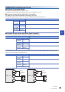
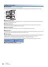
■Output terminal
One common terminal is used for 4 or 8 relay output points.
The common terminal blocks can drive loads of different circuit voltage systems (for example,100 V AC and 24 V DC).
■External power supply
Use an external power supply of 30 V DC or less or 240 V AC or less (250 V AC or less when the module does not comply
with CE, UL, cUL standards) for loads.
■Insulation of circuit
The PLC internal circuit and external load circuits are electrically insulated between the output relay coil and contact.
The common terminal blocks are separated from one another.
■Display of operation
When power is applied to the output relay coil, the LED is lit, and the output contact is turned on.
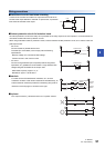
■Response time
The response time of the output relay from when the power is applied to the coil until the output contact is turned on and from
when the coil is shut off until the output contact is turned off is approx. 10 ms.
■Output current
At a circuit voltage of 240 V AC or less (250 V AC or less when the module does not comply with CE, UL, cUL standards), a
resistance load of 2 A per point or an inductive load of 80 VA or less (100 V AC or 200 V AC) can be driven.
For the life of the contact for switching an inductive load, refer to Page 89 Inductive load.
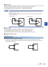
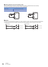
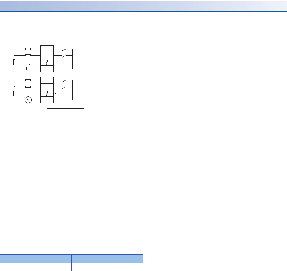
When an inductive load is switched, connect a diode (for commutation) or a surge absorber in parallel with this load.
■Open circuit leakage current
There is no leakage current when the outputs are OFF.
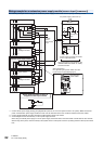
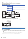
DC circuit AC circuit
Diode (for commutation) Surge absorber
PLCs
Load
24 V DC
Fuse
Y0
Y1
COM0
Load
100 V AC
Fuse
Y4
Y5
COM1