


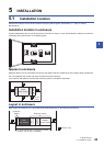
5 INSTALLATION
5.5 Connection Methods for CPU Module and Extension Devices
71
5
5.5 Connection Methods for CPU Module and
Extension Devices
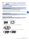
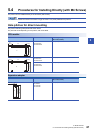
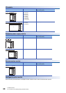
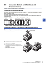
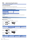
This section explains the connection methods for extension devices.
Connection of extension devices
The connection method varies depending on the combination of products, i.e., the CPU module, expansion board, expansion
adapters, and extension modules.
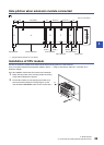
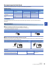
The connection methods are explained with the following configuration example.
For connection method for FX5 extension power supply module (FX5-1PSU-5V), refer to MELSEC iQ-F FX5-1PSU-5V
HARDWARE MANUAL.
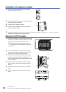
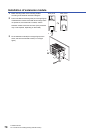
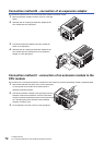
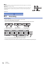
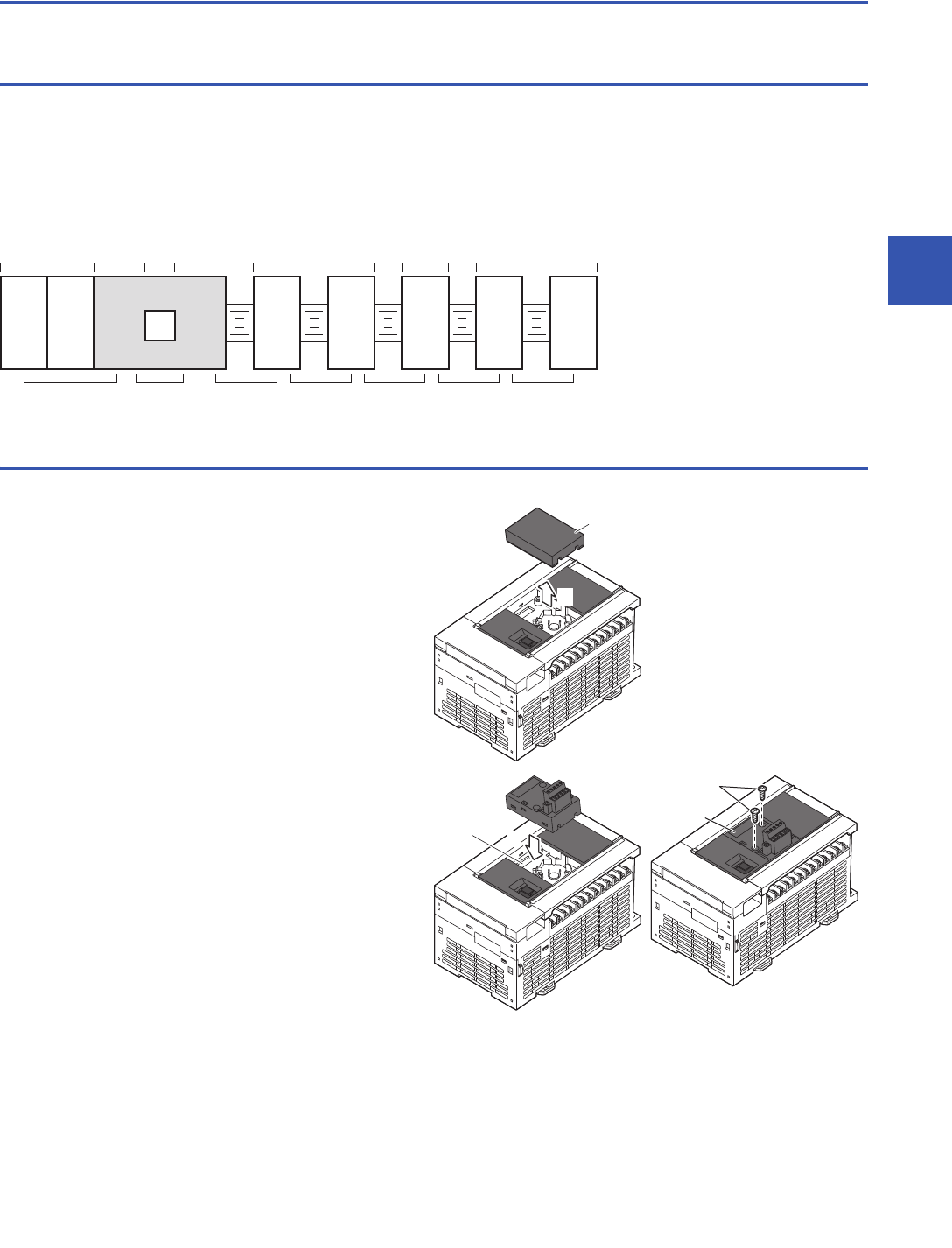
Connection method A - connection of an expansion board
This subsection explains how to connect the expansion board to the CPU module.
1. Remove the expansion board connector cover from the
front face of the CPU module.
2. Connect the expansion board to the expansion board
connector (C in the right figure).
3. Fix the expansion board (E in the right figure) with
provided M3 tapping screws (D in the right figure) to the
CPU module.
• Tightening torque: 0.3 to 0.6Nm
FX5
extension module
Bus conversion
module
FX5U
CPU module
Expansion
adapter
Expansion
board
FX3
extension module
Connection
method B
Connection
method A
Connection
method C
Connection
method D
Connection
method D
Connection
method E
Connection
method D
1
Expansion board
connector cover
C
2
D
E