


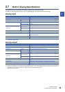
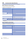
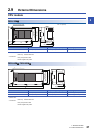

2 SPECIFICATIONS
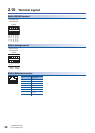
2.10 Terminal Layout
29
2
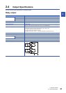
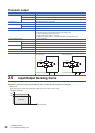
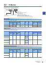
Power, input/output terminal block
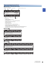
■Interpretation of terminal block layout
■ FX5U-32M
■FX5U-64M
• Indication of power supply terminals
[L] and [N] terminals.
For external wiring, refer to Page 79 Power Supply Wiring.
• Indication of 24 V DC service power supply
[0V] and [24V] terminals.
• Indication of input terminal
For external wiring, refer to Page 83 Input Wiring.
• Indication of output terminals connected to common (COM)
One common terminal covers 4 or 8 output points.
The output number (Y) connected to common is the range inside the thick "separation line."
For transistor output (source) type, the "COM" terminal is the "+V" terminal.
X0S/S 0 V
24 V
N
L1
2
3
4
5
6
7
X10
11
12
13
14
15
16
17
FX5U-32MR/ES
Input terminal
Output terminal
Partition
[•] Vacant terminal (Do not use)
Output terminals
connected to COM3
Y42
3
COM1
1
Y0
COM0
5
6
7
Y10
11
12
13
Y14
15
16
17
COM2 COM3
Common terminal
(4 points/common)
24 V DC service
power supply
Power supply
terminals
Y42
3 +V11
Y0
+V0 5
6
7
Y10
11
12
13
Y14
15
16
17+V2 +V3
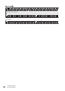
FX5U-32MT/ESS
X0S/S 0V
24VNL1
2
3
4
5
6
7
X10
11
12
13
14
15
16
17
Y42
3
COM1
1
Y0
COM0
5
6
7
Y10
11
12
13
Y14
15
16
17
COM2 COM3
FX5U-32MR/ES, FX5U-32MT/ES
FX5U-64MT/ESS
0VS/S 0V
24VNL 24V
X0
1
2
3
4
5
6
7
X10
11
12
13
14 2216 X20
2115 17 23
24
25
26
27
X30
31
32
33
34
35
36
37
Y42
3
COM1
1
Y0
COM0
5
6
7
Y10
11
12
13
Y14
15
16
17
COM2 COM3
2422Y20
21 23
COM4
25
26
27
32Y30
33
34
35
COM5
36
31 37
Y42
3 +V11
Y0
+V0 5
6
7
Y10
11
12
13
Y14
15
16
17+V2 +V3
2422Y20
21 23+V4 25
26
27
32Y30
33
34
35
+V536
31 37
FX5U-64MR/ES, FX5U-64MT/ES