


5 INSTALLATION
5.3 Procedures for Installing on and Detaching from DIN Rail
65
5
5.3 Procedures for Installing on and Detaching from
DIN Rail
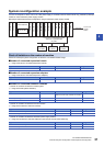
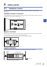
The CPU module can be installed on a DIN46277 rail (35 mm (1.38") wide).
Preparation for installation
Connecting extension devices
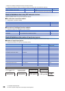
Some extension devices must be mounted on the CPU module before the module is installed in the enclosure.
• Connect expansion adapters to the CPU module before mounting the PLC in the enclosure.
• Mount extension modules in the enclosure after mounting the CPU module in the enclosure.
• Expansion boards can be mounted on the CPU module after it is installed in the enclosure.
• Batteries can be replaced without dismounting the CPU module from the enclosure. However, if an expansion board is
used, the CPU module must be removed.
Affixing the dust proof sheet
The dust proof sheet should be affixed to the ventilation slits before beginning the installation and wiring work.
For the affixing procedure, refer to the instructions on the dust proof sheet.
Always remove the dust proof sheet when the installation and wiring work is completed.
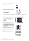
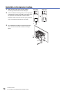
Installation of CPU module
Connect the expansion adapter to the CPU module before mounting the PLC in the enclosure.
For the connection method of the expansion adapter, refer to Page 72 Connection method B - connection of an
expansion adapter.
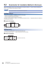
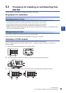
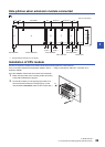
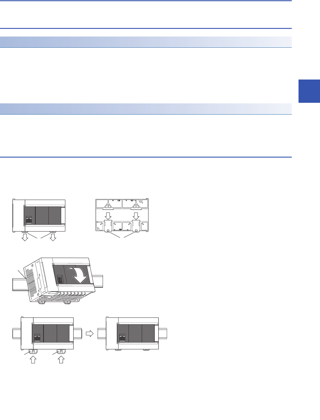
1. Push out all DIN rail mounting hooks (A in the following figure).
2. Fit the upper edge of the DIN rail mounting groove (B in the following figure) onto the DIN rail.
3. Lock the DIN rail mounting hooks (C in the following figure) while pressing the PLC against the DIN rail.
1
A
A
1
11
B
C
3
C
3