11
2.3. Wiring
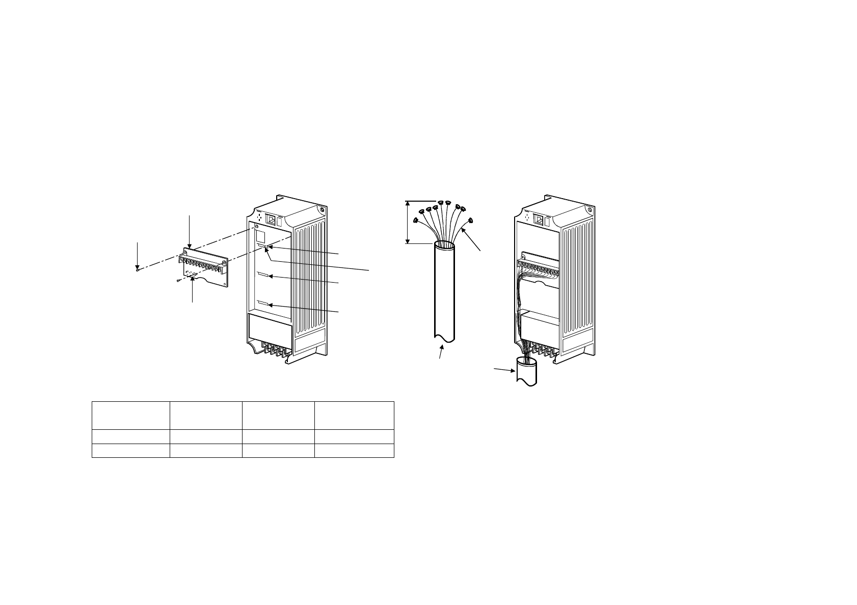
Route the cables so that they do not take up a large space in the control circuit terminal block wiring area of the
option unit.
Wire the twisted pair shielded cable after stripping its sheath to make its cables loose. Also, protect the shield cable
of the twisted pair shielded cable to ensure that it will not make contact with the conductive area.
Note: During wiring, do not leave wire off-cuts in the inverter. They can cause a fault, failure or malfunction.
Option side
connector
Option unit
Accessor
y
screw
(
2 pcs.
)
Slot 1
Inverter side
connector
Slot 2
Slot 3
Cable routin
g
Inverter
(
Without cover
)
Shield cable
Twisted pair shielded cable
L
Sheath Stripping Dimensions for Shield Cable
Inverter
Capacity
Slot 1 Slot 2 Slot 3
0.4K to 3.7K L: 350mm L: 300mm L: 250mm
5.5K to 55K L: 270mm L: 220mm L: 170mm
I.ORIENTATION CONTROL


