39
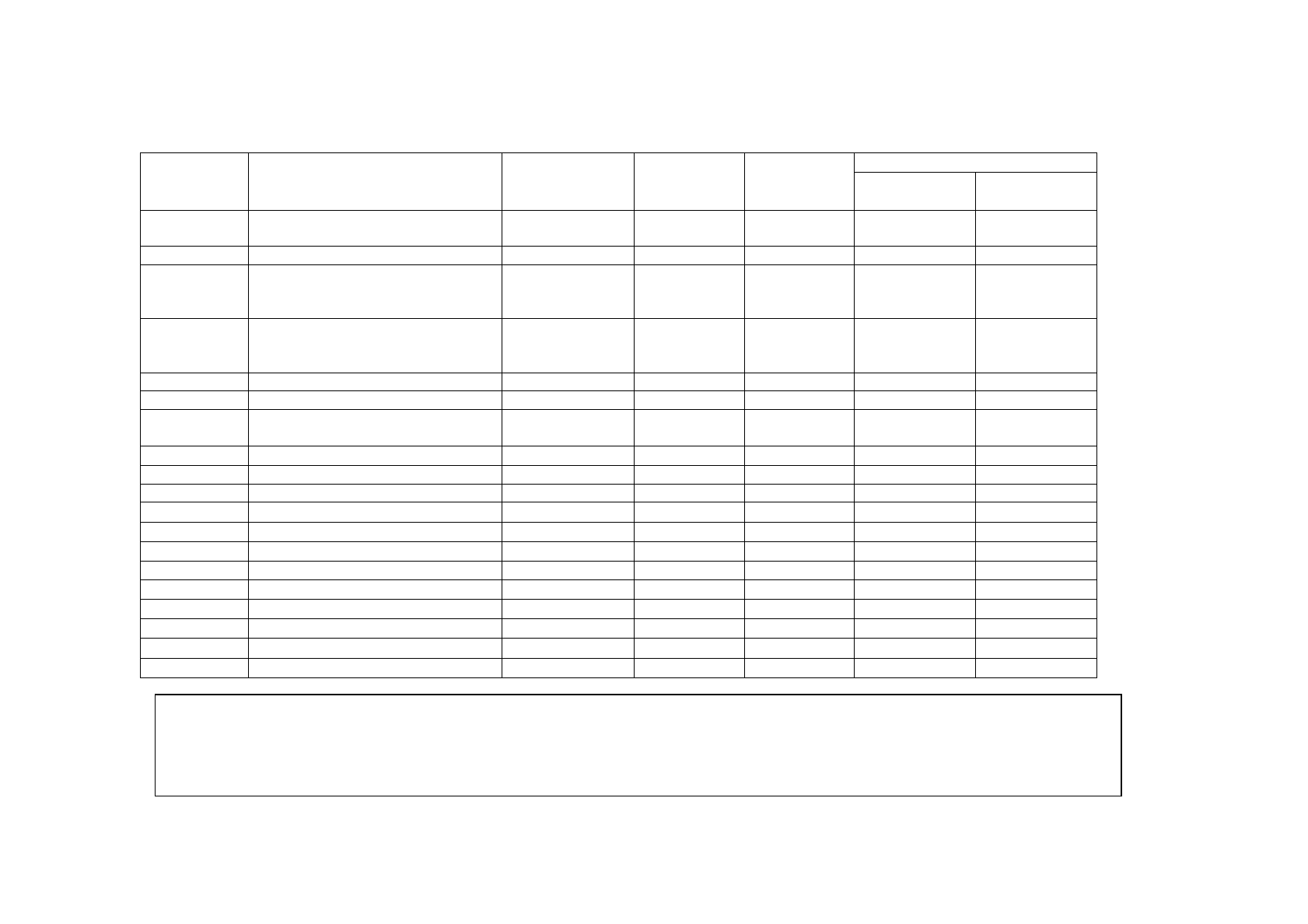
4.5. Related Parameter List
Control ModeParameter
Number Name
Setting Range Minimum
Setting
Increments
Factory
Setting
PLG feedback
control
Vector
control
22 Torque limit level (Stall prevention
operation level) (Note 1)
0 to 200%, 9999 0.1% 150%
(Note 3)
29 Acceleration/deceleration pattern 0, 1, 2, 3, 4 1 0
(Note 4)
(Note 4)
144 Number of motor poles (Speed
setting switch-over) (Note 1)
0, 2, 4, 6, 8, 10,
102, 104, 106,
108, 110
14
162 Automatic restart after
instantaneous power failure
selection
0, 1, 2 1 0
285 Overspeed detection frequency 0 to 30Hz, 9999 0.01Hz 9999
359 PLG rotation direction 0, 1 1 1
367 Speed feedback range 0 to 400Hz,
9999
0.01Hz 9999
368 Feedback gain 0 to 100 0.1 1
369 Number of PLG pulses 0 to 4096 1 1024
370 Control mode selection 0, 1, 2 1 0
371 Torque characteristic selection 0, 1 1 1
372 Speed control P gain 0 to 200% 0.1% 100%
373 Speed control I gain 0 to 200% 0.1% 20%
374 Overspeed detection level 0 to 400Hz 0.01Hz 120Hz
375 Servo lock gain 0 to 150 1 20
380 Acceleration S pattern 1 0 to 50% 1% 0%
381 Deceleration S pattern 1 0 to 50% 1% 0%
382 Acceleration S pattern 2 0 to 50% 1% 0%
383 Deceleration S pattern 2 0 to 50% 1% 0%
Note: 1. When the FR-A5AP is not fitted, the function names in parentheses are used.
2. • in the Control Mode field indicates that the corresponding function is valid.
3. Functions as the stall prevention operation level.
4. The acceleration/deceleration pattern C setting (Pr. 29 = 4) is made valid when the FR-A5AP is fitted.


