13
Note: 1. When the motor with a PLG used is other than the standard motor with PLG (SF-JR), the pin numbers
are different. To reduce radiated noise, connect the shield wires of the PLG cables to the CG.
2. When orientation control is used with PLG feedback control, the PLG and 5V power supply may be
shared between these controls.
3. Couple the PLG in line with the motor with a speed ratio of 1 to 1 without any mechanical looseness.
4. Keep the accessory jumpers connected. However, when the same PLG is shared between the FR-A5AP
and another unit (e.g. NC) which is connected with a terminal resistor, the built-in terminal resistors are
not required and should be removed. (Terminal resistors: 100
)
5. Assign this function to any of the input terminals using Pr. 180 to Pr. 186 "input terminal function
selection".
6. Assign this function to any of the output terminals using Pr. 190 to Pr. 195 "output terminal function
selection".
7.When the stop position command is entered from outside the inverter (externally), the FR-A5AX inboard
option is required.
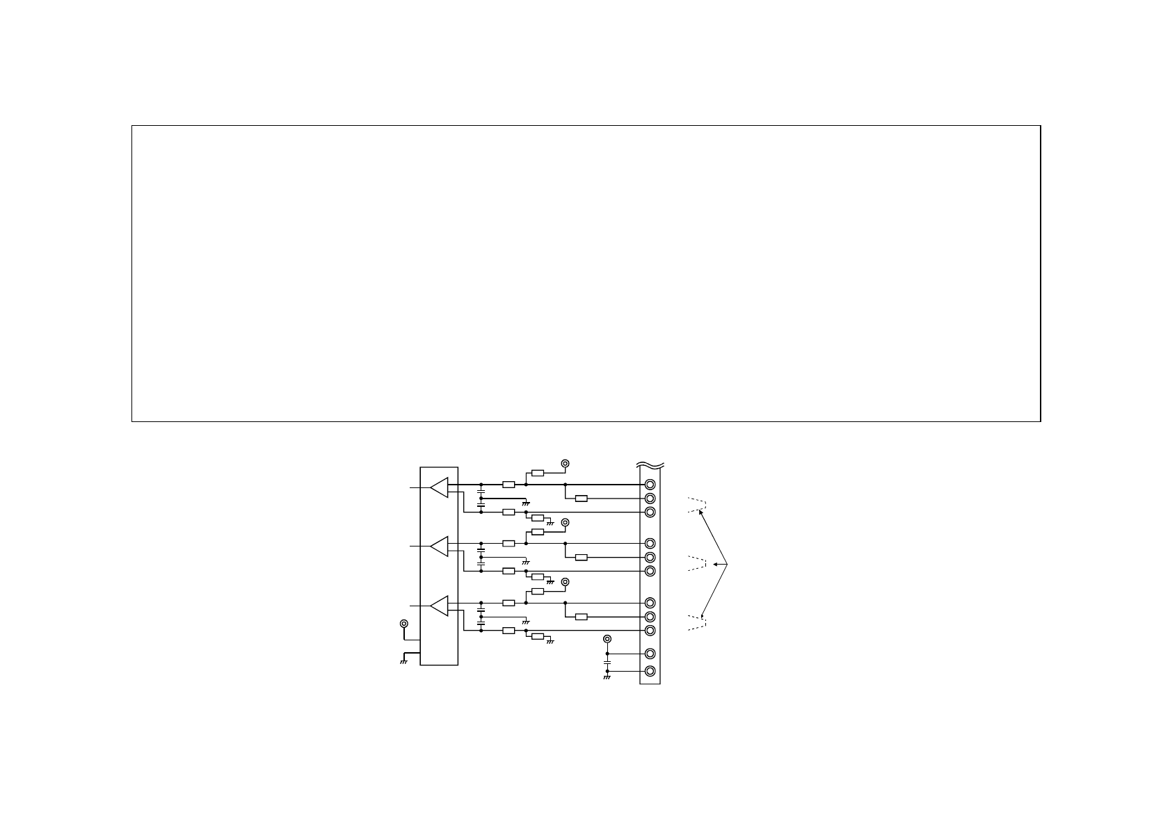
3.2. Input Circuit
1k
100
1000pF
PA1
PAR
PA2
PB1
PB2
PBR
5V
SG
+
-
1
F
100
1000pF
1000pF
1000pF
1000pF
PC1
PC2
PCR
1000pF
Jumpers
+
-
+
-
100
100
100
100
100
1k
1k
1k
1k
1k
100
100


