


55
5. Wiring Example
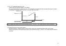
I. PULSE TRAIN INPUT
A pulse train signal can be used to enter the speed setting of the inverter.
Pr. 384 is factory set to "0" to make this function invalid.
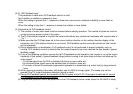
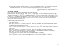
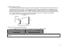
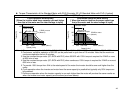
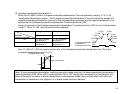
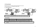
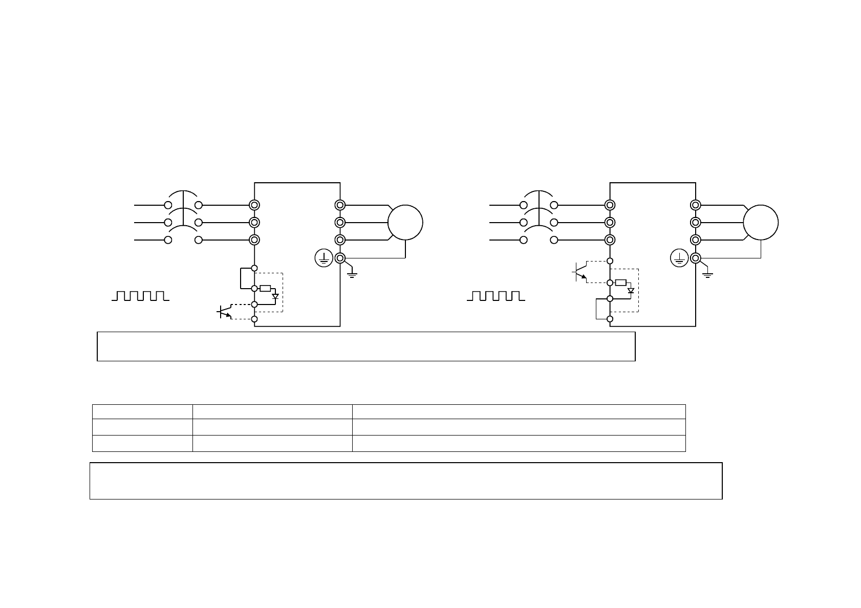
5.1. Wiring Example
NFB
IM
PC
PIN
PO
SD
FR-A5AP
R
(
L1
)
S
(
L2
)
T
(
L3
)
U
V
W
NFB
IM
PC
PIN
PO
SD
FR-A5AP
R
(
L1
)
S
(
L2
)
T
(
L3
)
U
V
W
Power
suppl
y
Input pulses
Open collector input
Inverter
Motor
or
Power
suppl
y
Input pulses
Open
collector
input
Inverter
Motor
Note: This option unit must be wired using the open collector system to operate it properly.
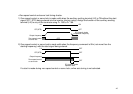
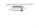
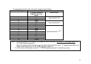
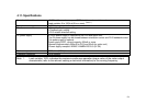
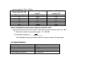
5.2. Terminals
Symbol Terminal Description
PIN Pulse input terminal 1
Terminal used to enter a pulse train of 0 to 100kpps
(Note)
PO Pulse input terminal 2
Terminal used to enter a pulse train of 0 to 100kpps
(Note)
Note: Whether an input pulse is entered into PIN or PO depends on the wiring. Refer to Section 5.1 "Wiring
Example".