


33
Mod el 5454 Operat ing Procedures
061121
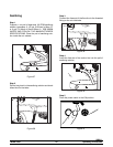
Step 4
Press the PUMP keypad. Lower the draw handles and
draw off all th e cleaning s olution. Once the solution
stops flowing from the door spouts, close the draw
handles and press the W ASH and P UMP keypads to
stop operation.
Disassembly
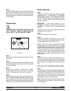
Step 1
BE SURE THE POWER SWITCH IS IN THE
“OFF” POSI TION. CHECK TO MAKE SURE NO
LIGHTS ARE LIT ON THE CONTROL PANEL.
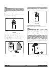
Figure 65
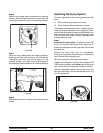
Step 2
Remove the restrictor caps from the bottom of each
door s pout.
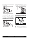
Step 3
Remove the spinner blades from the bottom of each
door spout by lift ing the slip collar on the coupling and
lowering the blade.
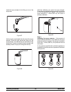
Step 4
Remove the handscrews, freezer door , beater,
scraper blades, and drive shaft from the freezing
cylinder. Take these parts to the sink for cleaning.
Step 5
Remove the air/mix pump. Unscrew the flare line from
the mix feed tube. Pull the retaining pin out of the pump
collar and slide the collar down. Tilt the air/m ix pump
away from the machine, and take the entire assembly
to the sink for further disassembly and brush cleaning.
Brush Cleaning
Step 1
Prepare a sink with a n approved cleaning solution
(example: Kay- 5R or Stera- SheenR). USE WARM
W ATE R AND FOLLOW THE MANUFACTURER’S
SPECIFICATIONS. If an approved cleaner other than
Kay- 5R or Stera- SheenR is used, dilute according
to label instructions.
IMPORTANT: Follow label directions, as too
STRONG of a solution c an cause parts damage, while
too MILD of a solution will not provide adequate
cleaning.
Make sure all b rushes provided with the freezer ar e
available for brush cleaning.
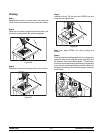
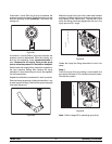
Step 2
Remove the seal from the drive shaft.
Step 3
Remove th e gasket, front bearing, pivot pin, draw
handles, draw valves, prime plug and syrup hole plugs
from the fr eezer door . Remove all o- rings.
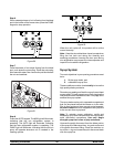
Note: To remove o- rings, use a single service towel
to gras p the o- ring. Apply pressure in an upward
direction until the o- ring pops out of its groove. With
the other hand, push the top of the o- ring forward, and
it will roll out of the groove and can be easily removed.
If there is more than one o- ring to be removed, always
remove the rear o- ring first. This will allow the o- ring
to slide over the forward rings without falling into the
open grooves.
Step 4
Remove the flare line, suction line, retaining pin, mix
inlet fit ting, spring and poppet, valve body, and piston
from t he pump cylinder. Remove all o- rings and check
bands. Remove the weighted end from the suction
line.
Wit h clean ed and sanitized parts t rays available:
Step 5
Thoroughly brush clean all disassembled par ts in the
cleaning solution, making sure alllubricantand m ixfilm
is removed. Take parti cular care to brush c lean the
draw valve core in the freezer door. Plac e all the
cleaned parts in t heir proper places on the cleanedand
sanitized par ts tr ays to air dr y overnight.
Note: Never leave the mix probe immersed in water .
Rinse the probe in the cleaning solution and allow it to
air dry overnight.