


RLC-PRC006-EN10
Application
Considerations
Leaving Water Temperature Limits
Trane air-cooled Series R chillers have
three distinct leaving water categories:
standard, low temperature, and ice
making. The standard leaving solution
temperature range is 40 to 60°F/4.4 to
15.6°C. Low temperature machines
produce leaving liquid temperatures less
than 40°F/4.4°C. Since liquid supply
temperature setpoints less than
40°F/4.4°C result in suction temperatures
at or below the freezing point of water, a
glycol solution is required for all low
temperature machines. Ice making
machines have a leaving liquid
temperature range of 20 to 60°F/-6.7 to
15.6°C. Ice making controls include dual
setpoint controls and safeties for ice
making and standard cooling
capabilities. Consult your local Trane
sales engineer for applications or
selections involving low temperature or
ice making machines. The maximum
water temperature that can be circulated
through an evaporator when the unit is
not operating is 108°F/42°C.
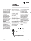
Leaving Water Temperature out of
Range
Many process cooling jobs require
temperature ranges that cannot be met
with the minimum and maximum
published values for the Model RTAC
evaporator. A simple piping change can
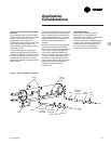
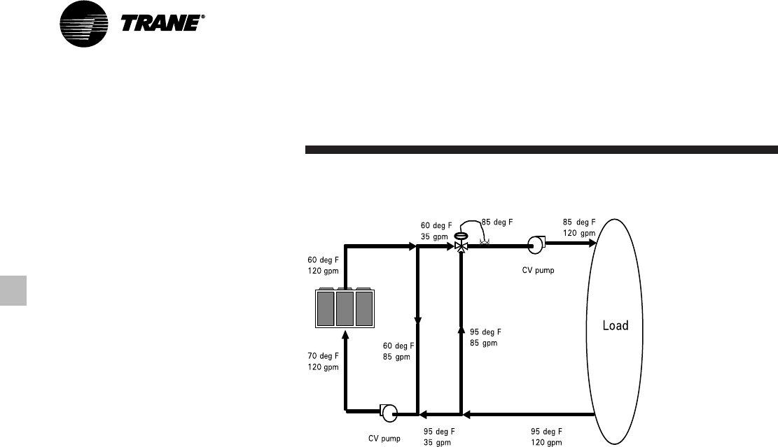
alleviate this problem. For example: A
laboratory load requires 120 gpm
[7.6 l/s] of water entering the process at
85°F [29.4°C] and returning at 95°F
[35°C]. The accuracy required is better
than the cooling tower can give. The
selected chiller has adequate capacity,
but a maximum leaving chilled water
temperature of 60°F [15.6°C].
In Figure 5, both the chiller and process
flow rates are equal. This is not
necessary. For example, if the chiller had
a higher flow rate, there would simply be
more water bypassing and mixing with
warm water.
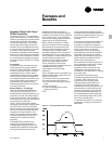
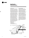
Supply Water Temperature Drop
The performance data for the Trane air-
cooled Series R chiller is based on a
chilled water temperature drop of 10°F/
5.6°C. Chilled water temperature drops
from 6 to 18°F/ 3.3 to 10°C may be used
as long as minimum and maximum
water temperatures and flow rates are
not violated. Temperature drops outside
this range are beyond the optimum
range for control and may adversely
affect the microcomputer’s ability to
maintain an acceptable supply water
temperature range. Further, temperature
drops of less than 6°F/3.3°C may result in
inadequate refrigerant superheat.
Sufficient superheat is always a primary
concern in any refrigerant system and is
especially important in a package chiller
where the evaporator is closely coupled
to the compressor. When temperature
drops are less than 6°F/3.3°C, an
evaporator runaround loop may be
required.
Variable Flow in the Evaporator
An attractive chilled water system option
may be a variable primary flow (VPF)
system. VPF systems present building
owners with several cost-saving benefits
that are directly related to the pumps.
The most obvious cost savings result
from eliminating the secondary
distribution pump, which in turn avoids
the expense incurred with the associated
piping connections (material, labor),
electrical service, and variable-frequency
drive. Building owners often cite pump-
related energy savings as the reason that
prompted them to install a VPF system.
With the help of a software analysis tool
such as System Analyzer
™
, TRACE
™
, or
DOE-2, you can determine whether the
anticipated energy savings justify the
use of variable primary flow in a
particular application. It may also be
easier to apply variable primary flow in
an existing chilled-water plant. Unlike the
“decoupled” system design, the bypass
can be positioned at various points in the
chilled-water loop and an additional
pump is unnecessary. The evaporator on
the Model RTAC can withstand up to 50
percent water flow reduction as long as
this flow is equal to or above the
minimum flow rate requirements. The
microprocessor and capacity control
algorithms are designed to handle a
maximum of 10% change in water flow
rate per minute in order to maintain ±
0.5°F leaving evaporator temperature
control.
Figure 5 — Temperature Out of Range System Layout