


RLC-PRC006-EN12
Application
Considerations
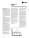
Short Water Loops
The proper location of the temperature
control sensor is in the supply (outlet)
water connection or pipe. This location
allows the building to act as a buffer and
assures a slowly changing return water
temperature. If there is not a sufficient
volume of water in the system to provide
an adequate buffer, temperature control
can be lost, resulting in erratic system
operation and excessive compressor
cycling. A short water loop has the same
effect as attempting to control from the
building return water. Typically, a two-
minute water loop is sufficient to prevent
problems. Therefore, as a guideline,
ensure the volume of water in the
evaporator loop equals or exceeds two
times the evaporator flow rate. For a
rapidly changing load profile, the
amount of volume should be increased.
To prevent the effect of a short water
loop, the following items should be
given careful consideration: A storage
tank or larger header pipe to increase the
volume of water in the system and,
therefore, reduce the rate of change of
the return water temperature.
Applications Types
• Comfort cooling.
• Industrial process cooling.
• Ice/thermal storage.
• Low temperature process cooling.
Typical Unit Installation
Outdoor HVAC equipment must be
located to minimize noise and vibration
transmission to the occupied spaces of
the building structure it serves. If the
equipment must be located in close
proximity to a building, it could be
placed next to an unoccupied space such
as a storage room, mechanical room,
etc. It is not recommended to locate the
equipment near occupied, sound
sensitive areas of the building or near
windows. Locating the equipment away
from structures will also prevent sound
reflection, which can increase levels at
property lines, or other sensitive points.
When physically isolating the unit from
structures, it is a good idea to not use
rigid supports, and to eliminate any
metal-to-metal or hard material contact,
when possible. This includes replacing
spring or metal weave isolation with
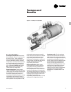
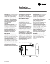
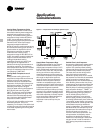
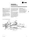
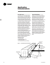
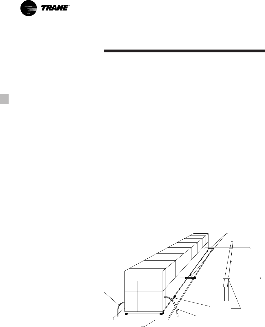
elastomeric isolators. Figure 7 illustrates
isolation recommendations for the
RTAC.
Elastomeric
Vibration
Eliminators
Avoid using the
chiller to support
chiller water
piping.
Neoprene
Isolators
Flex Conduit
Power Wiring
Concrete Base
Flex Conduit
Control Power
Figure 7 — Unit Isolation Recommendations