


45RLC-PRC006-EN
Electrical
Data
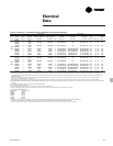
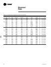
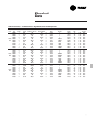
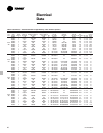
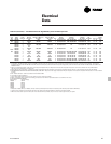
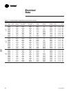
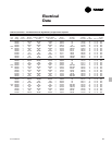
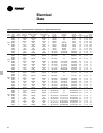
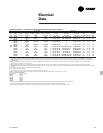
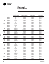
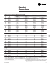
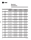
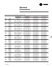
Table E-3 (Continued) — Unit Electrical Data for High Efficiency at High Ambient Operation
Unit Wiring Motor Data
# of Max. Fuse, HACR Rec. Time Compressor (Each) Fans (Each)
Unit Rated Power MCA (3) Breaker or MOP (11) Delay or RDE (4) RLA (5) XLRA (8) YLRA (8) Qty. Control
Size Voltage Conns (1) Ckt 1/Ckt 2 Ckt 1/Ckt 2 Ckt 1/Ckt 2 Qty Ckt 1/Ckt 2 Ckt 1/Ckt 2 Ckt 1/Ckt 2 Ckt 1/Ckt 2 kW FLA kW (7)
RTAC 400/50/3 1 855 1000 1000 4 198-198-168-168 1089-1089-896-896 354-354-291-291 26 1.5 2.8 1.59
375 400/50/3 2 485/412 600/500 600/500 4 198-198/168-168 1089-1089/896-896 354-354/291-291 14/12 1.5 2.8 1.59
200/60/3 1 NA
200/60/3 2 960/960 1200/1200 12001200 4 386-386/386-386 NA 701-701/701-701 14/14 1.5 6.5 1.59
230/60/3 1 NA
230/60/3 2 847/847 1000/1000 1000/1000 4 336-336/336-336 NA 571-571/571-571 14/14 1.5 6.5 1.59
RTAC 380/60/3 1 NA
400 380/60/3 2 505/506 700/700 600/600 4 203-203/203-203 1060-1060/1060-1060 345-345/345-345 14/14 1.5 3.5 1.59
460/60/3 1 798 800 800 4 168-168-168-168 878-878-878-878 285-285-285-285 28 1.5 3.0 1.59
460/60/3 2 420/420 500/500 500/500 4 168-168/168-168 878-878/878-878 285-285/285-285 14/14 1.5 3.0 1.59
575/60/3 1 640 700 700 4 134-134-134-134 705-705-705-705 229-229-229-229 28 1.5 2.5 1.59
575/60/3 2 337/337 450/450 400/400 4 134-134/134-134 705-705/705-705 229-229/229-229 14/14 1.5 2.5 1.59
400/50/3 1 920 1000 1000 4 198-198-198-198 1089-1089-1089-1089 354-354-354-354 28 1.5 2.8 1.59
400/50/3 2 485/485 600/600 600/600 4 198-198/198-198 1089-1089/1089-1089 354-354/354-354 14/14 1.5 2.8 1.59
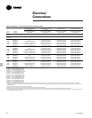
Notes:
1. As standard, 140-250 ton (60 Hz) units and 140-200 ton (50 Hz) units have single point power connections. Optional dual point power connections are available. As standard,
275-500 ton (60 Hz) units and 250-400 ton (50 Hz) units have dual point power connections. Optional single point power connections are available on 380V, 460V, 575 V/60 Hz and
400V/50 Hz units.
2. Max Fuse or HACR type breaker = 225 percent of the largest compressor RLA plus 100 percent of the second compressor RLA, plus the sum of the condenser fan FLA per NEC 440-22.
Use FLA per circuit, NOT FLA for the entire unit).
3. MCA - Minimum Circuit Ampacity - 125 percent of largest compressor RLA plus 100 percent of the second compressor RLA plus the sum of the condenser fans FLAs per NEC 440-33.
4. RECOMMENDED TIME DELAY OR DUAL ELEMENT (RDE) FUSE SIZE: 150 percent of the largest compressor RLA plus 100 percent of the second compressor RLA and the sum of the condenser
fan FLAs.
5. RLA - Rated Load Amps - rated in accordance with UL Standard 1995.
6. Local codes may take precedence.
7. Control kW includes operational controls only. Does not include evaporator heaters.
8. XLRA - Locked Rotor Amps - based on full winding (x-line) start units. YLRA for wye-delta starters is ~1/3 of LRA of x-line units.
9. VOLTAGE UTILIZATION RANGE:
Rated Voltage Utilization Range
200/60/3 180-220
230/60/3 208-254
380/60/3 342-418
460/60/3 414-506
575/60/3 516-633
400/50/3 360-440
10. A separate 115/60/1, 20 amp or 220/50/1, 15 amp customer provided power connection is needed to power the evaporator heaters (1640 watts).
11. If factory circuit breakers are supplied with the chiller, then these values represent Maximum Overcurrent Protection (MOP).
12. When the circuit breaker option is ordered, two circuit breakers will be provided (one per circuit) for both single and dual point power.