


FORM 160.55-O1 (604)
113
YORK INTERNATIONAL
A printer can be connected to the Control Center’s
Microboard to print the following reports. The screen
from which each report can be generated is listed in
pa ren the sis.
• Status - Present system parameters (Printer,
Home)
• Setpoints - Present programmed values of all set-
points (Printer, Setpoints)
• Schedule - Present value of programmed daily
sched ule (Printer, Schedule)
• Sales Order - Information on Sales Order Screen
(Print er, Sales Order)
• History - System parameters at the time of the last
normal stop, last fault while running and last 10
faults, whether running or not (Printer, History)
• Cycling or Safety shutdown initiated Print - Snap-
shot of all system parameters at instant of shut down.
Automatically occurs if printer is connected at time
of shutdown.
• Adaptive Capacity Control (ACC) surge Map
- Sys tem conditions at instant all surge points were
mapped. (Compressor Motor Variable Speed Drive
ap pli ca tions; requires SERVICE access level)
(Print er, ACC)
• Trend (Flash Memory card version C.MLM.
02.02.xxx and later) - Prints a snap shot of the ex-
isting trend screen data or prints new data col lect ed
af ter the trend print key is pressed.
The printer can be permanently connected to the Con trol
Center or connected as required to produce a re port. If
permanently connected, a DATA LOGGING fea ture
can produce a Status report automatically, be gin ning
at an Operator selected start time and oc cur ring at an
Operator selected interval thereafter.
The following Þ gures are examples of the different print
reports. Solid State Starter application print reports
shown. Electro-mechanical starter and Variable Speed
Drive reports are similar but print parameters ap pli ca ble
to those devices.
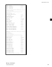
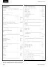
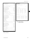
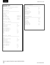
• Figure 44 - Status
• Figure 45 - Setpoints
• Figure 46 - Schedule
• Figure 47 - Sales Order
• Figure 48 - History
• Figure 49 - Security Log (Flash Memory Card ver-
sion C.MLM.02.03.xxx and later)
• Figure 50 - Trend (Flash Memory Card version
C.MLM.02.02.xxx and later)
• Figure 51 - Custom Screen
• Figure 52 - Adap tive Capacity Control New Map
point Report
• Figure 53 - Adaptive Capacity Control
Existing Map points Report
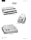
PRINTERS
The following Printers can be used. Printers must be
equipped with an RS-232 Serial interface.
• Okidata –
Models: 182,182 turbo, 184 turbo
Dimensions: 14 in. wide x 10.5 in. deep
Paper: 8.5 in. wide
Type: Dot matrix impact
Purchase: 800-OKIDATA
• Weigh-Tronix –
Models: 2600, 1220
Dimensions: 2.3 in. wide x 2.8 in. deep
Paper: 2.25 in. wide
Type: Dot matrix impact
Purchase: USA 800-982-6622
International 707-527-5555
• Seiko –
Model: DPU414-30B (Power supply PW4007-U I
re quired)
Dimensions: 6.3 in. wide x 6.7 in. deep
Paper: 4.4 in. wide
Type: Thermal
Purchase: Reptron Electronics, Inc
Phone: 800-800-5441 ext. 4686
Fax: 813-891-4056
Attn: Nancy Arthur, Account Mgr.
(narthur@reptron.com)
The Control Center provides the required formatting
control codes for the printers above when the printer
is selected on the PRINTER Screen in the instructions
below. These codes are transmitted through the serial
interface to the printer to provide a proper print for mat.
Different printers require different formatting control
codes. Oth er printers might provide proper op er a tion
when connected to the Control Center. How ev er, the
print format may not be correct or as desired. Proceed
with caution and use the following guidelines if an un-
list ed printer is selected:
1. All must be capable of RS-232 Serial com mu ni c-
a tions.
2. Primary differences between printers involve the for-
mat ting control codes required by the printer. These
3