


YORK INTERNATIONAL
8
FORM 160.55-O1 (604)
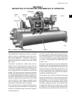
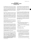
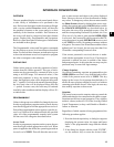
FIG. 2 – REFRIGERANT FLOW-THRU CHILL ER
PREROTATION VANES
(See Detail A)
SUCTION
COOLER
ELIMINATOR
OIL COOLER
LD00924
FLOW CON-
TROL
SUB-COOL-
CON-
DISCHARGE
BAFFLE
DISCHARGE
COMPRESSOR
able oriÞ ce meters the ß ow of liquid re frig er ant to the
cooler to com plete the refrigerant cir cuit.
The major components of a chiller are selected to han dle
the refrigerant, which would be evaporated at full load
design conditions. However, most systems will be called
upon to deliver full load capacity for only a relatively
small part of the time the unit is in operation.
CAPACITY CONTROL
The major components of a chiller are selected for full
load capacities, therefore capacity must be controlled
to maintain a constant chilled liquid temperature leav-
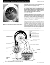
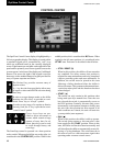
ing the cooler. Prerotation vanes (PRV), located at the
en trance to the compressor impeller, compensate for
vari a tion in load (See Fig. 2, Detail A).
The position of these vanes is automatically controlled
through a lever arm attached to an electric motor lo cat ed
outside the compressor housing. The automatic adjust-
ment of the vane position in effect provides the perfor-
mance of many different compressors to match various
load conditions from full load with vanes wide open to
minimum load with vanes completely closed.
7619A(D)
DETAIL A – COMPRESSOR PREROTATION VANES
Description of System and Fun da men tals of Operation