


FORM 160.55-O1 (604)
131
YORK INTERNATIONAL
Hz immersion type. A separate three phase pow er sup-
ply is required except when ordered with a YORK Solid
State Starter or Variable Speed Drive. A gravity ß ow oil
res er voir is pro vid ed to feed the bearings and gears dur-
ing coast down in the event of a power failure.
CAPACITY RE DUC TION - Prerotation vanes (PRV)
mod u late the unit capacity from 100% to 10% of de sign,
on normal air conditioning jobs. The prerotation vanes
are air foil-shaped and made of man ga nese bronze. An
external, electric PRV operator au to mat i cal ly con trols
the vane position through a sim ple, re li able link age.
SHAFT SEAL - The com pres sor drive shaft seal
con sists of a spring-loaded, pre ci sion lapped car bon
ring, high tem per a ture elastomer O-ring static seal, and
stress-re lieved, pre ci sion lapped cast iron collar. The
seal fea tures a small face area and low rub bing speed. It
pro vides an ef Þ cient seal under bothVacuum and pres-
sure conditions. The seal is oil-ß ooded at all times and
is pres sure-lu bri cat ed dur ing compressor op er a tion.
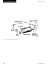
OPEN MO TOR - The 3600 RPM open motor is a
drip-proof, squir rel cage, induction type constructed
to YORK design speciÞ cations by na tion al ly-known
man u fac tur ers. Stan dard low voltage (208 through
600V-3Ph-60/50 Hz) motors are available for full-volt-
age (across-the-line) or re duced-voltage (solid state, star
delta or auto transformer) start ing. Standard high volt age
(2300 through 4160V-3Ph60/50 Hz) motors are avail able
for full-volt age (across-the-line) or reduced-volt age (pri-
ma ry re ac tor or auto trans form er) starting. Open close
cou pled motors are built with a cast iron adapter ß anged
be tween the motor and compressor. This unique de sign
allows the mo tor to be coupled to the com pres sor.
MOTOR TER MI NAL BOX - The casing is fab ri -
cat ed of heavy gauge steel. There are six terminals
(three for high volt age) in the terminal box. Provisions
are fur nished for 208 through 600 volts for three-lead
types of starting (solid state, across-the-line, and auto
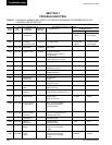
trans form er). Mo tor terminal lugs are furnished with
the YORK Current Guard Starter and the Variable
Speed Drive mount ed in the pow er section. Over load/
overcurrent trans form ers (CTs) are fur nished as listed
below; in motor ter mi nal box, as fol lows:
5
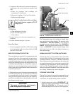
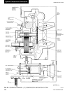
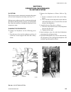
CASING - The casing is ac ces si ble with ver ti cal cir cu lar
joints and fab ri cat ed of close-grain cast iron. The mo tor
as sem bly is com plete ly removable from the com pres sor
rotor and scroll assembly. Com pres sor cast ings are de-
signed for 15 PSIG working pres sure and hy dro stat i cal ly
pressure tested at 50 PSIG.
COMPRESSOR - The rotor assembly consists of a
heat treated alloy steel drive shaft (integral with pin ion
gear) and a light weight, high strength, fully shroud ed
cast alu mi num impeller. The impeller is designed for
bal anced thrust. The im pel ler is dy nam i cal ly bal anced
to in sure vi bra tion free op er a tion and is overspeed test ed
for safe ty.
BEARINGS - Insert type journal and thrust bearings
are fab ri cat ed of alu mi num alloy and are precision bored
and ax i al ly grooved.
INTERNAL GEARS - Single he li cal gears with
crowned teeth are em ployed so that more than one tooth
is in con tact at all times to pro vide even dis tri bu tion of
the compressor load with quiet operation. Gears are in te -
gral ly as sem bled in the compressor rotor sup port and are
oil Þ lm lu bri cat ed. Each gear is in di vid u al ly mount ed in
jour nal bearings with individual thrust bear ings to in sure
prop er bal ance of forces from the im pel ler and mo tor.
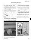
LUBRICATION SYS TEM - YORK lu bri cat ing oil
is force fed to all bear ings and Þ ltered by an ex ter -
nal ly mounted 15 mi cron replaceable car tridge oil
Þ lter equipped with service valves. An au to mat ic oil
re cov ery sys tem re turns oil to the com pres sor that has
mi grat ed into the re frig er ant system. Heat is re moved
from the oil by a re frig er ant-cooled oil cooler, located
in the evap o ra tor. All oil piping is completely factory-
in stalled and test ed. A thermostatically con trolled heater
is sup plied in the oil res er voir to limit the amount of
re frig er ant ab sorbed by the oil when the compressor is
not op er at ing.
Oil (under pressure) is supplied from the oil reservoir by
an internally-mounted sub mers ible oil pump. Oil Pump
motors are available in 208 through 600V-3Ph-60/50 Hz
to match the application and are supplied com plete with
starter and current sensing overloads for ex tra pro tec tion.
The oil reservoir heater is 1000 watts, 115V-1Ph-60/50
SECTION 5
SYSTEM COMPONENTS DESCRIPTION -
COMPRESSOR / MOTOR ASSEMBLY