


FORM 160.55-O1 (604)
99
YORK INTERNATIONAL
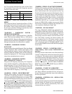
“STARTER – HIGH SUPPLY LINE VOLTAGE”
(Mod “A” Solid State Starter”)
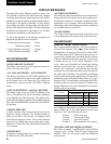
The voltage in any phase of the AC Power Line Volt age
supplying the Solid State Starter has increased to the
high line voltage threshold for 20 continuous sec onds.
The chiller will automatically restart when the voltage
returns to the restart level. The thresholds are as fol-
lows:
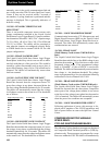
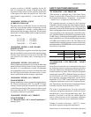
Supply Voltage Range (Volts) Shutdown (Volts) Restart (Volts)
380 415 414
400 436 435
415 454 453
440-480 524 523
550-600 655 654
Supply Voltage Range disabled none N/A
MOD “B” SOLID STATE STARTER
CYCLING SHUT DOWN MES SAG ES
“LCSSS – INITIALIZATION FAILED”
When AC Power is restored to the system after a pow er
failure, an initialization process occurs wherein the
OptiView Con trol Center attempts to establish com mu -
ni ca tions through the serial communications link with
the Liquid Cooled Solid State Starter. If com mu ni ca tions
are not es tab lished within 10 consecutive at tempts, a
Cycling shut down is performed and this message is
displayed. The Control Center attempts to establish
com mu ni ca tions un til suc cess ful.
“LCSSS – SERIAL COMMUNICATIONS”
After communications have been successfully es tab -
lished in the INITIALIZATION process, the OptiView
Control Center initiates a data transmission to the Liq uid
Cooled Solid State Starter on the serial com mu ni ca tions
link every 2 seconds. After these com mu ni ca tions have
been established, if the Control Center does not receive
a reply within 10 consecutive attempts, a Cy cling shut-
down is performed and this message is dis played. This
same Cycling shutdown is performed, along with the
same message, if the Liquid Cooled Sol id State Starter
does not receive a response from the con trol center
after 10 consecutive attempts to com mu ni cate with the
Control Center after INITIALIZATION has been suc-
cess ful ly completed. The Control Center at tempts to
es tab lish communications until successful.
“LCSSS SHUTDOWN – REQUESTING FAULT
DATA . . .”
The Liquid Cooled State Starter Logic/Trigger Board
has shut down the chiller but the OptiView Control
Cen ter has not yet received the cause of the fault from
the LCSSS, via the serial communications link. The
LCSSS shuts down the chiller by opening the Motor
Controller LCSSS Stop Contacts (K1 relay located on
the start er Logic/Trig ger Board and connected between
TB6-16 and TB6-53 in the OptiView Control Center).
The Microboard, in the Control Center then sends a
request for the cause of the fault to the Logic/Trigger
Board over the serial com mu ni ca tions link. Since serial
com mu ni ca tions are initiated every 2 seconds, this mes-
sage is typically displayed for a few seconds and then
re placed with one of the below listed fault messages.
“LCSSS – STOP CONTACTS OPEN”
Refer to “LCSSS SHUTDOWN – REQUESTING
FAULT DATA ...” above. If the OptiView Control
Cen ter’s Microboard does not receive the cause of
a starter initiated shutdown with 20 seconds of the
shut down, it is as sumed it is not forthcoming and that
mes sage is re placed with this message. The chiller can
be started when the Motor Controller LCSSS Stop
Con tacts close.
A missing interlock jumper between Start er Log ic/Trig ger
Board J1-1 and J1-12 will also produce this mes sage.
“LCSSS – POWER FAULT”
The Liquid Cooled Solid State Starter Logic/Trigger
Board has detected that the compressor motor current in
one or more phases has decreased to <10% of the FLA
for a minimum of 1 line cycle. This check is in hib it ed
during the Þ rst 4 seconds of SYSTEM RUN and until
the motor current is >25% of the FLA. The chiller will
automatically restart upon completion of SYSTEM
COASTDOWN.
“LCSSS – LOW PHASE X TEMPERATURE SEN-
SOR”
The Liquid Cooled Solid State Starter Logic/Trigger
Board has detected that the temperature of the starter
phase A, B or C (designated as X in the message) Sil i con
Controlled RectiÞ er (SCR) Module has decreased to
<37°F. This would generally be indicative of a dis con -
nect ed or defective sensor. If all three SCR Mod ules
are indicating a temperature of <37°F, the SCR Module
cooling pump turns on. This is accomplished by discon-
necting all three sensors. This feature allows Ser vice
Technicians to run the cooling pump while Þ ll ing the
cooling system by disconnecting plugs P2, P3 and P4
in the LCSSS.
“LCSSS – RUN SIGNAL”
The Liquid Cooled Solid State Starter receives two
start signals from the OptiView Control Center si mul -
2