


YORK INTERNATIONAL
128
FORM 160.55-O1 (604)
System Op er at ing Pro ce dures
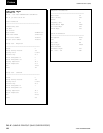
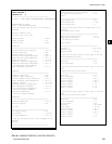
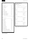
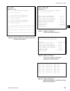
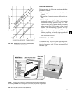
An optional sta tus printer is available for this purpose;
or, Fig. 48 shows a log sheet used by YORK personnel
for recording test data on chillers. It is avail able from
the factory in pads of 50 sheets each under Form No.
160.44-F6 and may be ob tained through the nearest
YORK ofÞ ce. Automatic data logging is possible by
con nect ing the optional printer and programming the
DATA LOG GER function.
An ac cu rate record of read ings serves as a valuable
ref er ence for op er at ing the system. Readings taken
when a system is newly in stalled will establish normal
con di tions with which to compare later readings.
For ex am ple, dirty condenser tubes may be indicated
by higher than normal tem per a ture differences be tween
leav ing con dens er water and refrigerant leaving the
condenser.
OPERATING INSPECTIONS
By following a regular in spec tion using the display read-
ings of the OptiView Control Cen ter, and main te nance
pro ce dure, the op er a tor will avoid se ri ous op er at ing dif-
Þ cul ty. The following list of in spec tions and pro ce dures
should be used as a guide.
Daily
1. Check OptiView Control Center dis plays.
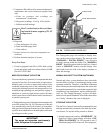
2. If the compressor is in operation, check the bear-
ing oil pressure by pressing “OIL SUMP” key to
read the dis play on the Control Center. Also check
the oil level in the oil reservoir. Drain or add oil if
nec es sary.
3. Check entering and leaving con dens er water pres-
sure and tem per a tures for com par i son with job de-
sign con di tions. Condenser water tem per a tures can
be checked by press ing “CONDENSER” dis play
key.
4. Check the en ter ing and leaving chilled liquid tem-
per a tures and evaporator pressure for comparison
with job design conditions. This can be ac com plished
by press ing the “EVAPORATOR” key and the “RE-
FRIG ER ANT PRES SURES” key.
5. Check the condenser sat u ra tion temperature (based
upon condenser pres sure sensed by the con dens er
trans duc er). Press the “CONDENSER” key.
6. Check the com pres sor dis charge temperature. Press
“COMPRESSOR” key. During nor mal operation
dis charge tem per a ture should not ex ceed 220°F.
7. Check the com pres sor motor voltage and current
(amps) at E-M starter (or Variable Speed Drive), or
on the OptiView Control Cen ter motor display for
Sol id State Start er units.
8. Check for any signs of dirty or fouled con dens er
tubes. (The tem per a ture dif fer ence between water
leav ing con dens er and liquid re frig er ant leav ing the
con dens er should not ex ceed the difference re cord ed
for a new unit by more than 4°F.)
9. Verify proper water treatment.
10. If the chiller is con trolled by a YORK Variable Speed
Drive, check the op er at ing lights on the logic sec tion.
(Re fer to 160.00-O1)
11. Monitor Graphic Display for Warning Messages.
Weekly
1.Check the re frig er ant charge. (See “Checking the
Refrigerant Charge”, page 140)
Quarterly
1. Change the purge unit de hy dra tor at least quarterly,
or more of ten if required.
2. Clean purge foul gas strainer.
3. Perform chemical anal y sis of oil.
4. Clean water strainer on VSD (if equipped).
Semi-An nu al ly (or more of ten as re quired.)
1. Change and inspect com pres sor oil Þ lter el e ment.
2. Oil re turn system
a. Change dehydrator.
b. Check nozzle of eductor for foreign par ti cles.
3. Check con trols and safety cut outs.
4. Check level of coolant if equipped with SSS or
VSD.
Annually (more often if necessary.)
1. Drain and re place the oil in the com pres sor oil sump
(See “Oil Charging Procedure”, page 129).
2. Cooler and Condenser
a. Inspect and clean water strain ers.
b. Inspect and clean tubes as required.
c. Inspect end sheets.
d. Backß ush heat exchanger on VSD (if equipped).