


FORM 160.55-O1 (604)
129
YORK INTERNATIONAL
3. Compressor Drive Motor (See motor man u fac tur er’s
main te nance and service in struc tion sup plied with
unit)
a.Clean air passages and windings per
manufacturer’s in struc tions.
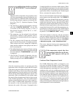
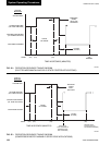
b. Meg motor wind ings - See Fig. 65 for de tails.
c. Relubricate ball bear ings.
Don’t over look motor drive end bear-
ing lo cat ed in mo tor support of F1, F2
com pres sors.
4. Purge unit.
a. Clean and in spect all valves.
b. Drain and ß ush purge shell.
c. Clean or i Þ c es.
5. Inspect and service elec tri cal com po nents as
necessary.
6. Perform chemical anal y sis of system.
Every Two Years
1. If unit is equipped with SSS or VSD, ß ush cool ing
circuit and replace with new coolant solution, YORK
Part # 013-02987-000.
NEED FOR PURGING THE SYSTEM
To assure sat is fac to ry operation, it is important that these
systems be kept free of moisture laden air and noncon-
densible gas es. Air in the system usually col lects in the
con dens er, blanketing some of the con dens ing surface,
causing the dis charge pressure and tem per a ture to rise,
re sult ing in high operating cost, and possibly surg ing, or
shut down of system by high pres sure cutout. Mois ture
in the system causes acid for ma tion which is de struc tive
to internal system parts.
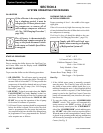
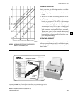
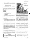
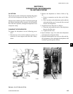
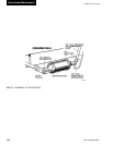
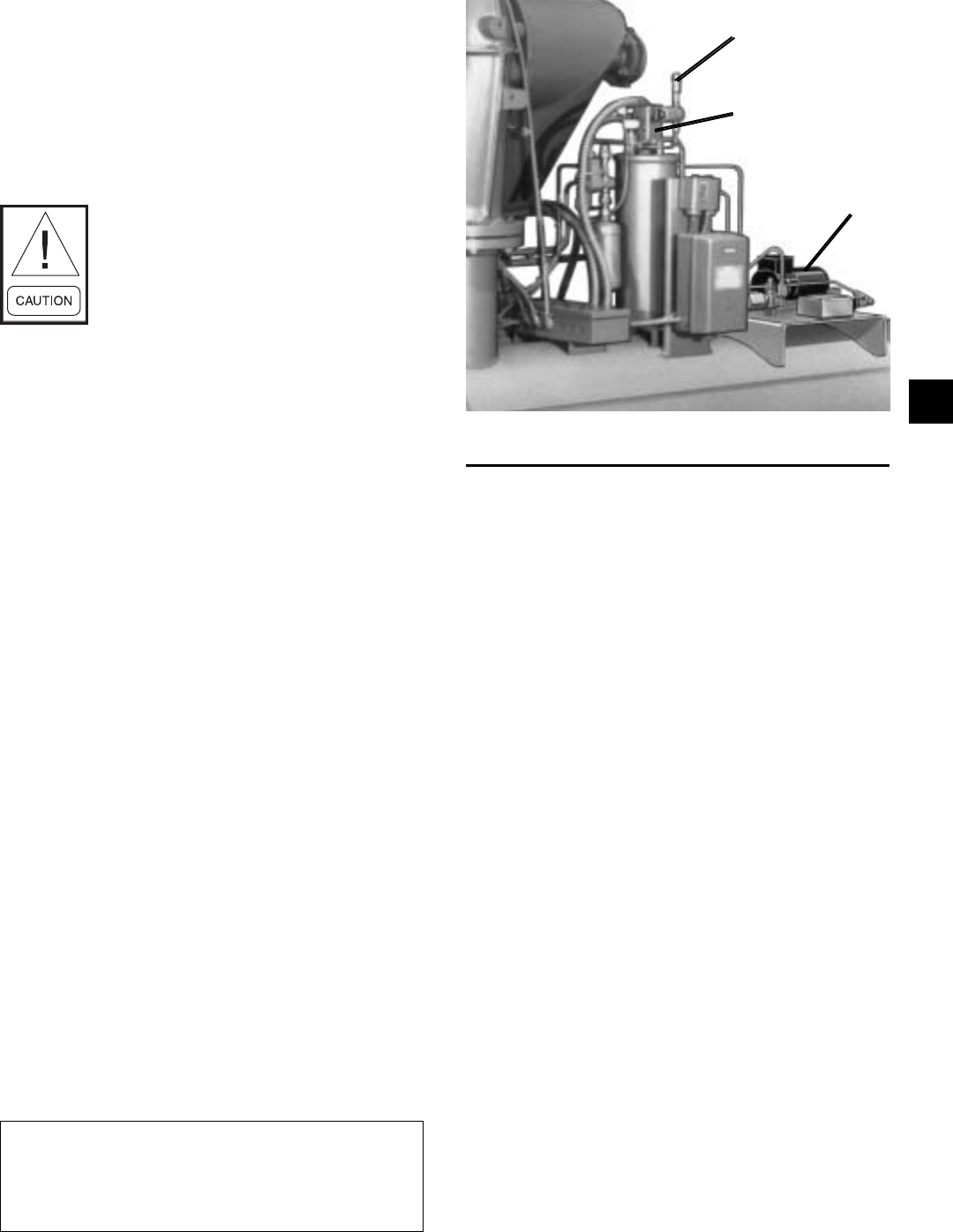
A Turboguard purge unit is fur nished and mounted at the
rear of the system (See Fig. 58). The purpose of this unit
is to au to mat i cal ly remove the mixture of nonconden-
sible gases and re frig er ant from the top of the con dens er,
expel the noncondensibles to the at mo sphere and return
the re frig er ant to the system.
IMPORTANT!
The purge unit operates con tin u ous ly
when the system is in operation.
FIG. 58 – TURBOGUARD PURGE UNIT
27046A(D)
CHECK VALVE
FLOAT SWITCH ASS’Y.
PUMP
The Turboguard purge unit in cludes a display mes-
sage on the control center dis play. The message reads
“WARN ING – EXCESS PURGE” if an ex ces sive
air leak is present with in the chill er. The “WARN ING
RE SET” should be pushed with the OptiView Control
Cen ter in “SER VICE” mode to reset the display. Leak
check and cor rect the leak if the dis play continues to
show this mes sage.
NORMAL AND SAFE TY SYS TEM SHUTDOWNS
Normal and safety system shutdowns have been built
into the chiller to protect it from dam age during certain
op er at ing conditions. There fore, it should be un der stood
that at certain pres sures and tem per a tures the system will
be stopped au to mat i cal ly by controls that respond to high
tem per a tures, low tem per a tures, and low and high pres-
sures, etc. The “Display Messages” section is an ex pla -
na tion of each spe ciÞ c shut down. If the chiller shuts down
on a “Safe ty” shut down the cause is dis played.
STOPPING THE SYSTEM
The OptiView Control Cen ter can be pro grammed to start
and stop au to mat i cal ly (max i mum, once each day) when-
ev er desired. To stop the chill er pro ceed as fol lows:
1. Push the compressor switch to “STOP/RESET”. The
OptiView Control Center display will show “SYS-
TEM COASTDOWN” for 150 seconds (6 min. if
Microboard jumper JP36 removed). The com pres sor,
4