


YORK INTERNATIONAL
12
FORM 160.55-O1 (604)
When in this position, the chiller will not run un der
any condition. For safe ty reasons, this po si tion is
re quired for many maintenance tasks to be com plet ed
(such as prox im i ty probe and vane cal i bra tion). In
ad di tion, the switch must be placed in this state
fol low ing a Safety shut down before the chill er is
al lowed to re start. This guar an tees that manual in ter -
ven tion has tak en place and the shut down has been
ac knowl edged.
The switch can only remain in this po si tion when
being acted upon by a man u al force. Once the user
has re leased the switch, it au to mat i cal ly re verts to
the RUN po si tion. Gen er al ly, this state only occurs
mo men tari ly as the operator at tempts to locally start
the unit. Once this po si tion has been sensed, if all
fault con di tions are cleared, the unit will en ter the
sys tem prelube (start se quence).
When in this position, the chiller is able to op er ate.
The switch spring-re turns to this state after it has
been tog gled to the START po si tion. When in this
state, the chiller is al lowed to function normally and
will also al low the chill er to au to mat i cal ly re start fol-
low ing a Cy cling shut down. The switch must be in
this state to re ceive a val id re mote start signal when
op er at ing under a re mote con trol source.
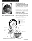
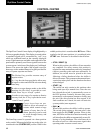
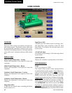
CONTROL CENTER
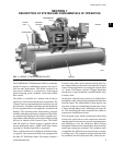
The OptiView Control Center display is high light ed by a
full screen graph ics display. This dis play is nested with in
a stan dard keypad and is sur round ed by “soft” keys
which are re de Þ ned based on the currently dis played
screen. Eight buttons are avail able on the right side of the
pan el and are primarily used for navigation between the
sys tem screens. At the base of the display are 5 ad di tion al
but tons. The area to the right of the key pad is used for
data entry with a stan dard numeric key pad provided for
en try of system setpoints and lim its.
The Decimal key provides accurate entry of
setpoint values.
A +/- key has also been provided to allow en try
of neg a tive values and AM/PM selection dur ing
time entry.
In order to accept changes made to the chiller
setpoints, the Check key is provided as a uni-
ver sal ‘En ter’ key or ‘Accept’’ symbol.
In order to reject entry of a setpoint or dismiss
an entry form, the ‘X’ key is provided as a uni-
ver sal ‘Can cel’ sym bol.
Cursor Arrow keys are pro-
vid ed to allow move ment on
screens which contain a large
amount of entry data. In ad-
di tion, these keys can be used
to scroll through his to ry and
event logs.
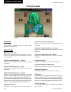
The Start/Stop control is op er at ed via a three-position
rocker switch. When toggled all the way to the right, it is
considered in the STOP/RESET position. When in the
middle position, this is considered the RUN state. When
toggled to the left-most position, it is considered in the
START state. Each state is described in detail below:
• STOP / RESET (O)
• START (◄)
• RUN ( )
00134VIP
FIG. 3
OptiView Control Center