


FORM 160.55-O1 (604)
147
YORK INTERNATIONAL
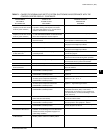
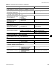
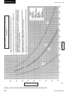
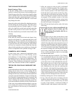
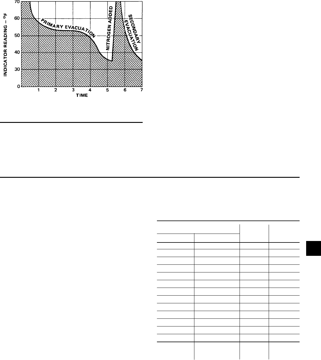
FIG. 64 – SATURATION CURVE
LD00474
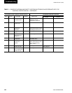
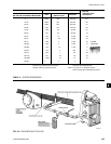
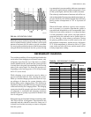
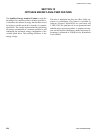
SHELL CODES
COOLER COMPRESSOR
G0, G1, G3 B 890 900
G0, G1, G3 C 890 900
H1, H3 − 970 975
J1, J3 − 1130 1125
K1, K3 − 1270 1275
G0, G1, G3 E 890 900
H1, H3 − 970 975
J1, J3 − 1130 1125
K1, K3 − 1270 1275
L1, L3 − 1390 1400
K4, K6 F 1390 1400
K7, K9 − 1530 1550
L4, L6 − 1590 1600
FACTORY
CHARGE SHIPPED
LBS.
When this point is reached, practically all of the air has
been evacuated from the system, but there is still a small
amount of moisture left. In order to provide a medium
for carrying this residual moisture to theVacuum pump,
nitrogen should be in tro duced into the system to bring
REFRIGERANT CHARGING
it to at mo spher ic pressure and the indicator tem per a ture
will re turn to approximately am bi ent tem per a ture. Close
off the system again, and start the second evac u a tion.
The relatively small amount of moisture left will be car-
ried out through theVacuum pump and the tem per a ture or
pressure shown by the indicator should drop uni form ly
until it reaches a tem per a ture of 35°F or a pres sure of
5mm Hg.
When theVacuum indicator registers this tempera-
ture or pres sure it is a positive sign that the system is
evac u at ed and de hy drat ed to the recommended limit.
If this level can not be reached, it is evident that there
is a leak somewhere in the system. Any leaks must be
cor rect ed before the in di ca tor can be pulled down to
35°F or 5mm Hg. in the primary evac u a tion. During
the pri ma ry pull down keep a careful watch on the wet
bulb indicator tem per a ture, and do not let it fall below
35°F. If the tem per a ture is allowed to fall to 32°F the
water in the test tube will freeze, and the result will be
a faulty tem per a ture reading.
To avoid the possibility of freezing the liquid within the
cooler tubes when charg ing an evacuated system, only
refrigerant vapor from the top of the drum or cyl in der
must be ad mit ted to the system until the system pres sure
is raised above the point corresponding to the freez ing
point of the cooler liquid. For water, the pres sure cor-
re spond ing to the freez ing point is 20.4 in Hg.Vacuum
for R-123 (at sea level).
While charg ing, every pre cau tion must be taken to
pre vent mois ture laden air from entering the sys tem.
Make up a suit able charging con nec tion from new cop-
per tubing to Þ t be tween the sys tem charging valve
and the Þ tting on the charging drum. This connection
should be as short as possible but long enough to per mit
suf Þ cient ß ex i bil i ty for chang ing drums. The charg ing
con nec tion should be purged each time a full con tain er
of re frig er ant is con nect ed and changing con tain ers
should be done as quickly as possible to min i mize the
loss of re frig er ant.
Refrigerant may be fur nished in drums con tain ing ei ther
100, 200 or 650 lbs. of re frig er ant. These drums are not
re turn able and they should be stored for future use if
it should ever become nec es sary to re move re frig er ant
from the system.
TABLE 4 – REFRIGERANT CHARGE
8