


YORK INTERNATIONAL
146
FORM 160.55-O1 (604)
Maintenance
EVACUATION AND DEHYDRATION OF UNIT
VACUUM TESTING
After the pressure test has been completed theVacuum
test should be conducted as follows:
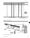
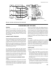
1. Connect a high ca pac i tyVacuum pump, with in di -
ca tor, to the sys tem charg ing valve as shown in
Fig. 63 and start the pump (see “Vacuum De hy -
dra tion”).
2. Open wide all sys tem valves, in clud ing the purge and
gauge valves. Be sure all valves to the at mo sphere
are closed.
3. Operate theVacuum pump in accordance with “Vac-
u um Dehydration” until a wet bulb tem per a ture of
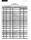
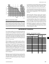
+32°F or a pressure of 5mm Hg. is reached. See Table
3 for cor re spond ing values of pres sure.
4. To im prove evac u a tion circulate hot water (not to
exceed 125°F) through the cooler and condenser
tubes to thor ough ly de hy drate the shells. If a source
of hot water is not readily avail able, a portable
wa ter heat er should be employed. DO NOT USE
STEAM. A sug gest ed meth od is to connect a hose
between the source of hot water under pressure and
the cool er head drain con nec tion, out the cooler vent
con nec tion, into the con dens er head drain and out the
con dens er vent. To avoid the pos si bil i ty of caus ing
leaks, the tem per a ture should be brought up slow ly
so that the tubes and shell are heated evenly. Close
the sys tem charg ing valve and the stop valve be tween
theVacuum indicator and theVacuum pump. (See Fig.
63) Then disconnect theVacuum pump leav ing the-
Vacuum indicator in place.
5. Hold theVacuum ob tained in Step 3 in the sys tem for
8 hours; the slightest rise in pressure in di cates a leak
or the pres ence of moisture, or both. If, after 8 hours
the wet bulb tem per a ture in theVacuum in di ca tor has
not risen above 40°F or a pres sure of 6.3mm Hg, the
sys tem may be con sid ered tight.
Be sure theVacuum indicator is valved
off while holding the systemVacuum
and be sure to open the valve be tween
theVacuum in di ca tor and the system
when check ing theVacuum af ter the 8
hour period.
6. If theVacuum does not hold for 8 hours within the
limits spec i Þ ed in Step 5 above, the leak must be
found and repaired.
VACUUM DEHYDRATION
To ob tain a sufÞ ciently dry system, the following in-
struc tions have been as sem bled to provide an ef fec tive
meth od for evacuating and dehydrating a system in
the Þ eld. Although there are several methods of de hy -
drat ing a system, we are recommending the fol low ing,
as it pro duc es one of the best results, and af fords a
means of obtaining accurate read ings as to the extent
of de hy dra tion.
The equip ment required to follow this method of de-
hy dra tion consists of a wet bulb indicator orVacuum
gauge, a chart showing the relation between dew point
tem per a ture and pressure in inches of mercury (vac u um),
(see Table 3) and aVacuum pump capable of pumping a
suitableVacuum on the system.
OPERATION
Dehydration of a refrigeration system can be ob tained
by this method because the water present in the sys tem
reacts much as a refrigerant would. By pulling down
the pres sure in the system to a point where its sat u -
ra tion tem per a ture is considerably below that of room
tem per a ture, heat will ß ow from the room through the
walls of the system and va por ize the water, allowing
a large percentage of it to be removed by theVacuum
pump. The length of time necessary for the de hy dra tion
of a system is de pen dent on the size or volume of the
sys tem, the ca pac i ty and efÞ ciency of theVacuum pump,
the room tem per a ture and the quantity of water present
in the sys tem. By the use of theVacuum in di ca tor as
suggested, the test tube will be evacuated to the same
pressure as the system, and the distilled water will be
maintained at the same saturation temperature as any
free water in the system, and this temperature can be
observed on the thermometer.
If the system has been pressure test ed and found to be
tight prior to evac u a tion, then the sat u ra tion tem per a ture
recordings should follow a curve sim i lar to the typ i cal
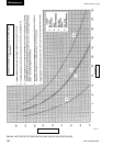
saturation curve shown as Fig. 64.
The tem per a ture of the water in the test tube will drop as
the pressure decreases, until the boiling point is reached,
at which point the temperature will level off and remain
at this level until all of the water in the shell is vapor-
ized. When this Þ nal va por iza tion has taken place the
pressure and temperature will con tin ue to drop until
eventually a tem per a ture of 35°F or a pressure of 5mm
Hg. is reached.