


FORM 160.55-O1 (604)
85
YORK INTERNATIONAL
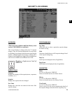
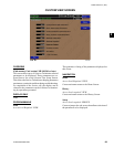
Select
Access Level Required: OPERATOR
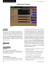
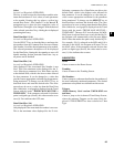
This key is used to enter the slot numbers and the min-
i mum and maximum Y-Axis values of each parameter
to be trended. Pressing this key places a yellow box
around Data Point 1 Slot Number. Use the ▲ and ▼
navigation keys to place the box around the value of
Data Points 1 through 6 to be changed. With the de sired
value selected, press the ✓ key. A dialog box is dis played
permitting data entry.
Data Point Slot # (1-6)
Access Level Required: OPERATOR
Use the SELECT key as described above and enter the
slot number from the Common Slots Screen or Master
Slot Number List of the desired parameter to be trend ed.
The selected parameter description will be displayed
for the Data Point. Setting this slot number to zero will
disable trending for that par tic u lar Data Point. Any or
all points can be dis abled.
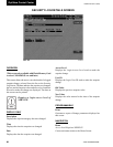
Data Point Min (1-6)
Access Level Required: OPERATOR
Only displayed if the Associated Slot Number is not
Zero. This is the minimum value displayed for the Y-
Axis. Selecting a parameter for a Data Point sets this
to the default value, which is the lowest value allowed
for that parameter. It can be changed to a value that
pro vides a more appropriate resolution for the pa ram e ter
being monitored. To change, use the SELECT key as
described above and enter the desired value. The value
must always be set to a value less than the Data Point
Max. Otherwise, a red graph is displayed on the Trend
Screen with the words “TREND MAX MUST BE >
TREND MIN”. If the parameter selected for this data
point is a digital type (on/off), this value must be set to
zero (0). Zero indicates the OFF state.
Data Point Max (1-6)
Access Level Required: OPERATOR
Only displayed if the associated slot number is not zero.
This is the maximum value displayed for the Y-Axis.
Se lect ing a parameter for a Data Point sets this to the
de fault value, which is the highest value allowed for
that pa ram e ter. It can be changed to a value that pro-
vides a more appropriate resolution for the parameter
being mon i tored. To change, use the SELECT key as
described above and enter the desired value. The value
must al ways be set to a value greater than the Data Point
Min. Otherwise, a red graph is displayed on the Trend
Screen with the words “TREND MAX MUST BE >
TREND MIN”. There are 20 Y-Axis divisions. If a MIN-
MAX span is selected that is not evenly divided by 20,
the Pro gram will automatically select the next higher
MAX val ue that makes the span evenly di vid ed by 20.
For ex am ple, if 0.0 is selected as the MIN and 69.0 is
selected as the MAX, the Program will insert 70.0 as
the MAX value. If the parameter se lect ed for this data
point is a digital type (on/off), this value must be set to
one (1). One indicates the on state.
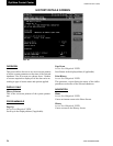
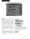
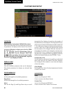
NAVIGATION
Home
Causes a return to the Home Screen.
Trending
Causes a return to the Trending Screen.
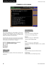
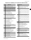
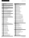
Slot Numbers
Causes a jump to a subscreen that lists the slot num bers of
the most commonly monitored parameters. The de sired
parameters to be plotted are selected from this screen.
Triggers
(Flash Memory Card version C.MLM.02.02.xxx
and later)
Causes a jump to the Advanced Trend Setup Screen,
where the start/stop Triggers can be setup. Only dis-
played if TRIGGERED has been selected as Chart
Type.
2