


YORK INTERNATIONAL
134
FORM 160.55-O1 (604)
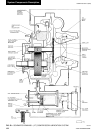
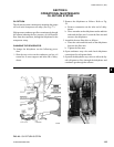
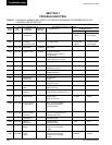
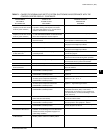
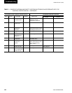
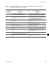
System Components De scrip tion
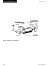
Victaulic grooves are welded to the water boxes. These
nozzle connections are suit able for Victaulic cou plings,
weld ing or ß anges (300 PSI has ß ang es). 1/2" cou pling
and separable well are lo cat ed in the entering and leav ing
chilled liquid nozzles for tem per a ture sensing el e ments.
Plugged 1/2" or 3/4" drain and vent connections are
pro vid ed in each water box.
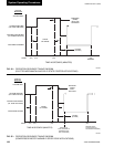
COOLER - The cooler is a hor i zon tal, ß ooded, shell-
and-tube type, with a dis tri bu tion system consisting
of a distributor trough to give uniform distribution
through out the shell length and a perforated distributor
plate, lo cat ed under the entire tube bundle, to equally
dis trib ute re frig er ant. Intermediate steel tube supports
are spaced at intervals of less than four feet. High ly ef-
Þ cient, alu mi num mesh eliminators are lo cat ed above
the tube bun dle to prevent liquid refrigerant carryover
into the compressor.
A liquid level sight glass is con ve nient ly located on the
side of the cooler to aid in de ter min ing proper re frig -
er ant charge.
CONDENSER - The con dens er is a hor i zon tal, shell-
and-tube type, with a dis charge gas bafß e to prevent di-
rect high ve loc i ty im pinge ment on the tubes. This baf ß e
is also used to dis trib ute the refrigerant gas ß ow prop er ly
for most ef Þ cient heat transfer. A purge con nec tion is
located in the con dens er for ef Þ cient elim i na tion of
noncondensibles. Intermediate steel tube sup ports are
spaced at in ter vals of less than four feet.
REFRIGERANT FLOW CON TROL - The ß ow con-
trol chamber is welded to the bottom of the con dens er to
allow complete drain age of liquid refrigerant from the
condenser. The chamber con tains a single Þ xed-oriÞ ce
ß ow control with no moving parts.
BURSTING DISC - A 2" or 3" frangible carbon burst-
ing disc relief device is located in the compressor suc-
tion line.
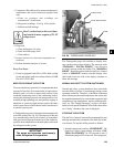
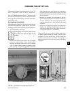
SOLID STATE STARTER (OP TION AL)
The Solid State Starter is a re duced-voltage liquid cooled
starter that controls and maintains a constant current
ß ow to the motor during start-up. The starter is mount ed
on the chiller. The power wiring from the start er to the
mo tor and from the starter control trans form er to the
Control Center is fac to ry wired and test ed. Available
for 200-600V-3Ph-60/50 Hz power; 2 or 3 barrel lug
connections per phase are provided on the starter. The
starter en clo sure is NEMA Type1 and is provided with
a hinged door with lock and key.
VARIABLE SPEED DRIVE (OPTIONAL)
A 460V-3ph-60/50 Hz Variable Speed Drive can be fac-
to ry pack aged with the chiller. It is de signed to vary the
compressor motor speed and prerotation vane position
by con trol ling the fre quen cy and voltage of the elec tri cal
pow er to the motor. Op er a tion al information is con tained
in Form 160.00-O1. The con trol log ic au to mat i cal ly
ad justs mo tor speed and com pres sor prerotation vane
po si tion for max i mum part load efÞ ciency by an a lyz ing
in for ma tion fed to it by sen sors located through out the
chiller.