


FORM 160.55-O1 (604)
13
YORK INTERNATIONAL
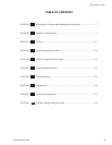
OVERVIEW
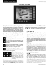
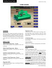
The new graphical display on each control pan el al lows
a wide variety of information to be pre sent ed to the
user. Each screen description in this document will be gin
with a section entitled Overview which will de scribe
the graphical elements on the screen and give a short
summary of the functions available. Each el e ment on
the screen will then be categorized into three dis tinct
groups: Display Only, Programmable and Nav i ga tion.
Below is a short description of what types of in for ma tion
are included in these groups.
The Programmable values and Navigation commands
are also subject to access level restrictions as de scribed
below. For each of these elements, an in di ca tion is giv en
to show the minimum access level required to program
the value or navigate to the subscreen.
DISPLAY ONLY
Values in this group are read-only parameters of in for -
ma tion about the chiller operation. This type of in for -
ma tion may be represented by a numerical value, a text
string or an LED image. For numerical values, if the
monitored parameter is above the normal operating
range, the high limit value will be displayed along with
the ‘>’ symbol; if it is below the normal operating range,
the low limit value will be displayed along with the
‘<’ sym bol. In some cases, the value may be rendered
in valid by other conditions and the display will use X’s
to in di cate this.
PROGRAMMABLE
Values in this group are available for change by the user.
In order to program any setpoints on the sys tem, the user
must Þ rst be logged in with the ap pro pri ate access level.
Each of the programmable values re quires a spe ciÞ c Ac-
cess Level which will be indicated beside the speciÞ ed
value. All of the pro gram ma ble controls in the system
fall into one of the categories described below:
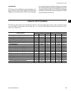
Access Level
In order to program any setpoints on the sys tem, the user
must Þ rst login with an appropriate ac cess level. When
power is applied to the chiller, the system begins with an
Access Level of VIEW. This will allow the user to navi-
gate to most screens and observe the values displayed
there. However, the user will not be allowed to change
any values. To change any values, the user must return to
the Home Screen (shown by de fault when pow er is ap-
plied to the system) and use the LO G IN but ton or uti lize
the CHANGE SETPOINTS key de scribed be low. At
this point, the user will be prompt ed to enter a User ID
and the corresponding Password. By default, the User
ID is zero (0). In order to gain stan dard OP ER A TOR
level access, the Pass word would be en tered as 9 6 7 5,
us ing the numeric keypad. OP ER A TOR ac cess reverts
to the VIEW lev el after 10 con tin u ous min utes without
a keypress. If a custom User ID and Pass word have been
deÞ ned (see User Screen ), the user may enter that User
ID and the cor re spond ing Password value.
If the correct password is received, the user is au tho -
rized with the appropriate Access Level. If an incorrect
pass word is entered, the user is notiÞ ed of the failure
and prompted again. At this point the user may retry the
password entry or cancel the login attempt.
Change Setpoints
On screens containing setpoints programmable at the
OPERATOR access level, a key with this label will be
visible if the present access level is VIEW. This key
brings up the Access Level prompt described above. It
allows the user to login at a higher Access Level with out
returning to the Home Screen. After login, the user may
then modify setpoints on that screen.
Setpoints
The control center uses the setpoint values to control the
chiller and other devices connected to the chiller system.
Setpoints can fall into several categories. They could be
numeric values (such as 45.0°F for the Leav ing Chilled
Liquid Temperature) or they could Enable or Disable a
feature or function.
Regardless of which setpoint is being programmed, the
following procedure applies:
1. Press the desired setpoint key. A dialog box ap pears
dis play ing the present value, the up per and low er
limits of the programmable range and the de fault
value.
2. If the dialog box begins with the word “ENTER”,
use the numeric keys to enter the desired value.
INTERFACE CONVENTIONS
2