


FORM 160.55-O1 (604)
125
YORK INTERNATIONAL
4
Any mal func tions which oc cur dur ing
“STOP/ RE SET” are also dis played.
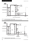
When the chiller is shut down, the prerotation vanes
will close au to mat i cal ly to pre vent loading the com-
pres sor on start-up. When the chill er starts to op er ate,
the fol low ing au to mat ic sequences are ini ti at ed: (Re-
fer to Fig. 54 & 55, “Operation Sequence Tim ing
Diagram”.)
1. The OptiView Con trol Center display mes sage
will read “SYSTEM PRELUBE” for the Þ rst
30 sec onds of the start ing sequence. (3 min. if
Microboard Pro gram Switch SW1-3 is “ON”;
“OFF” = 30 sec onds.)
2. The com pres sor vent line solenoid valve will open
af ter the Þ rst 5 minutes of unit operation. The so-
le noid will close au to mat i cal ly after the com pres sor
shuts down.
3. The 1R-1 con tacts of the 1R start relay will remain
open for the Þ rst 30 seconds of oil pump operation.
These con tacts will close, start ing the com pres sor
motor and the con dens er water pump at the end of
the 30 sec ond period.
4. The chilled liq uid pump contacts will close, start ing
the chilled liquid pump to allow liquid ß ow through
the cooler when the “COM PRES SOR” start switch
is energized.
5. After the Þ rst 30 seconds of operation, the com-
pres sor will start and the Graphic Control Center
dis play mes sage will read “SYSTEM RUN”.
Chiller Operation
After the com pres sor reaches its operating speed the
prerotation vanes will begin to open under the con trol
of the micro processor board or the logic section of the
Variable Speed Drive which senses the leaving chilled
liq uid tem per a ture. The unit capacity will vary to main-
tain the leaving chilled liquid temperature setpoint. The
prerotation vanes are mod u lat ed by an actuator under
the control of the microprocessor board or logic sec tion
of the Variable Speed Drive. The vane control rou tine
em ploys pro por tion al plus derivative (rate) con trol ac-
tion. A drop in chilled liquid temperature will cause
the actuator to close the prerotation vanes (and also
de creas es the speed of the mo tor if equipped with a
Vari able Speed Drive) to de crease chill er capacity. When
the chilled liquid tem per a ture ris es, the actuator will open
the prerotation vanes and in crease the com pres sor mo tor
speed of the chiller (if controlled by the Variable Speed
Drive), to in crease the capacity of the unit.
However, the cur rent draw (amperes) by the com pres sor
motor can not ex ceed the set ting of the “% CUR RENT
LIMIT” at any time during the unit operation, since the
Graphic Control Cen ter 30 to 100% three phase peak
current limit software function, plus the 3 phase 100%
solid state overload cur rent limiter (CM-2) on Electro-
Mechanical Starter applications or the solid state starter
current limit function will override the tem per a ture con-
trol func tion (or the logic section of the Vari able Speed
Drive) and pre vent the prerotation vanes from open ing
beyond the “% CUR RENT LIM IT” setting.
If the load continues to de crease, after the prerotation
vanes are entirely closed, the chiller will be shut down
by the Low Water Tem per a ture con trol (LWT) func tion
which is displayed on the Con trol Cen ter as: “LEAV ING
CHILLED LIQUID – LOW TEM PER A TURE”.
This occurs when the leav ing water tem per a ture falls
to programmed shutdown setpoint or 36°F, which ev er
is higher.
If the temperature setpoint has been
re pro grammed within the last 10 min-
utes, the LWT cutout is 36°F for 10
minutes.
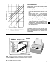
Condenser Water Tem per a ture Con trol
The YORK Millennium chiller is de signed to use
less pow er by tak ing ad van tage of lower than design
tem per a tures that are nat u ral ly produced by cooling
tow ers through out the op er at ing year. Exact control of
con dens er wa ter, such as a cooling tower bypass, is not
nec es sary for most in stal la tions. The chiller requires only
that the min i mum con dens er water temperature be no
low er than the val ue de ter mined by re fer ring to Fig. 56.
At start-up the en ter ing con dens er water tem per a ture may
be as much as 25°F cold er than the stand by return chilled
wa ter tem per a ture. Cooling tow er fan cy cling will nor-
mal ly pro vide ad e quate control of the en ter ing con dens er
wa ter tem per a ture on most in stal la tions.