86
DM Area Allocations Section 4-2
These bits show the status of FINS/TCP connections.
4-2 DM Area Allocations
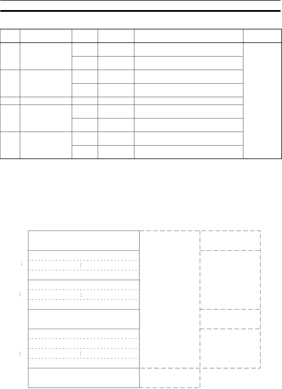
The various kinds of data are stored in the offset positions shown in the fol-
lowing diagram, from the beginning word in the area for each Unit.
The beginning word m is calculated by the following equation:
Beginning word m = D30000 + (100 x unit number)
Bit Switch Status Manipulated
by
Unit operation Reference
0 FINS/TCP Connec-
tion No.1
ON Unit Turned ON by the Unit when a connection is
established.
SECTION 6
FINS Commu-
nications Ser-
vice
OFF Unit Turned OFF by the Unit when the connection
is terminated.
1 FINS/TCP Connec-
tion No.2
ON Unit Turned ON by the Unit when a connection is
established.
OFF Unit Turned OFF by the Unit when the connection
is terminated.
to to to to to
14 FINS/TCP Connec-
tion No.15
ON Unit Turned ON by the Unit when a connection is
established.
OFF Unit Turned OFF by the Unit when the connection
is terminated.
15 FINS/TCP Connec-
tion No.16
ON Unit Turned ON by the Unit when a connection is
established.
OFF Unit Turned OFF by the Unit when the connection
is terminated.
Offset
Bit
Data direction Related communications services
Ethernet Unit to CPU Unit
m
m+1
m+8
m+9
m+16
m+17
m+18
m+28
m+88
m+98
m+99
15 08 07 00
TCP Socket No. 1 Connection Status
TCP Socket No. 8 Connection Status
Send Mail Status 1
Socket Services Parameter Area 1
Socket Services Parameter Area 2
Socket Services Parameter Area 8
IP Address Display/Setting Area
Send Mail function
Socket Services
Socket Services
Ethernet Unit to CPU Unit or
CPU Unit to Ethernet Unit
TCP Socket No. 1 Number of Bytes Received
TCP Socket No. 8 Number of Bytes Received
Send Mail Status 2
Send Mail function
Operation Manual, Construction of
Applications, Section 2
Operation Manual, Construction
of Applications, Section 6
Operation Manual, Construction
of Applications, Section 6
Operation Manual, Construction of
Applications, Section 2


