87
DM Area Allocations Section 4-2
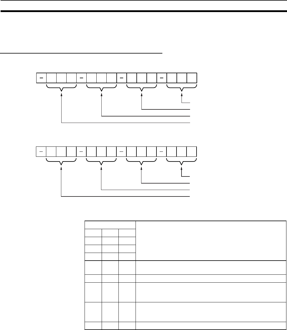
The meanings of the items shown in the above diagram are explained on the
following pages. For details regarding the related communications services
shown in the diagram, refer to the indicated sections.
Send Mail Status 1, 2 (Ethernet Unit to CPU Unit)
Send Mail Status 1
Send Mail Status 2
The transmission status of user mail, periodic mail, and error log mail are
stored in this word as shown in the following table.
While mail is being sent, the transmission status of the three bits each for
send condition settings 1 to 8, i.e., bits 02, 01, and 00; bits 06, 05, and 04; or
bits 10, 09, an 08 are 0, 0, and 1 respectively. After the transmission has been
completed normally, they become 0, 1, and 0. If the transmission is ended
with an error, they become 1, 1, and 0.
Check this transmission status in the ladder program as required.
m
Status of Send Condition Setting 1
Status of Send Condition Setting 2
Status of Send Condition Setting 3
1514131211109876543210
Status of Send Condition Setting 4
m+17
Status of Send Condition Setting 5
Status of Send Condition Setting 6
Status of Send Condition Setting 7
1514131211109876543210
Status of Send Condition Setting 8
Bits Status
02 01 00
06 05 04
10 09 08
14 13 12
OFF OFF OFF Mail is either waiting to be sent or can be sent using the Mail
Send Switch. No mail is being sent.
OFF OFF ON Mail is being sent.
OFF ON OFF Mail is either waiting to be sent or can be sent using the Mail
Send Switch. The previous mail transmission was completed
normally.
ON ON OFF Mail is either waiting to be sent or can be sent using the Mail
Send Switch. An error occurred in the previous mail transmis-
sion.
ON ON ON Mail cannot be sent (system setting error).


