130
Using FINS Applications Section 6-5
• Local Network Table
• Relay Network Table
None
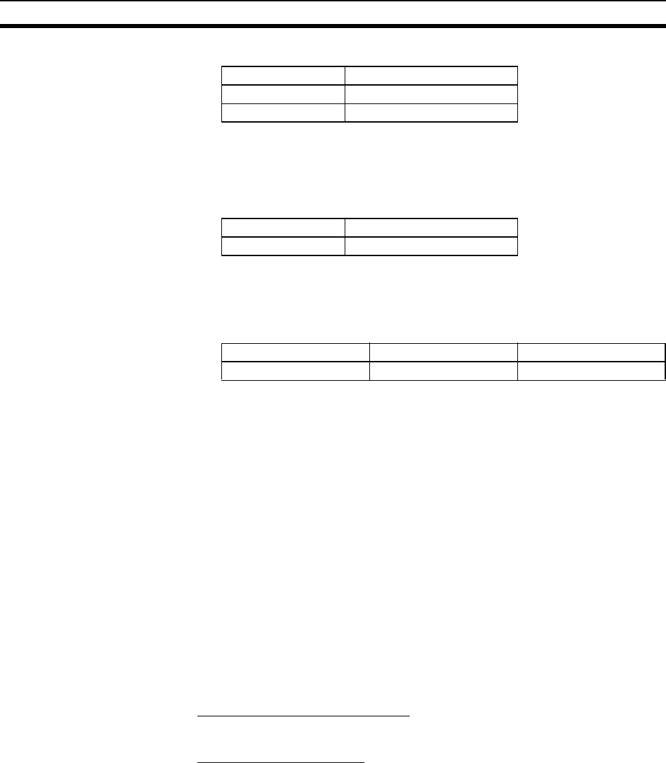
Example: PLC 2 and PLC 3 Routing Table Settings
• Local Network Table
• Relay Network Table
In order to relay from PLC2/3 to the final network number 1, it is necessary
to relay via node address 1 (i.e., the Controller Link Unit) on relay network
number 2.
2. Save the routing table file (File - Save local routing table file).
3. Select New from the Project Menu, and save with a file name. Then select
Add Device from the Project Menu. For each PLC, register a PLC with a
direct serial connection (node address: 0), and select it.
4. With CX-Integrator, select Open from the PLC Menu.
5. Select Routing table
− Setup, read the saved file, and select Options −
Transfer to PLC. Click Yes to transfer the routing tables to the connected
PLCs.
6-5-2 FinsGateway
FinsGateway Ver. 2003 must be used to communicate using FINS/TCP
between applications serving as communications drivers and CS1W-ETN21
or CJ1W-ETN21 Ethernet Units.
FinsGateway Ver. 3.@ or lower versions can be used, however, when commu-
nicating by the FINS/UDP method only.
■ Overview of Setup Methods
1. Starting FinsGateway Settings
Select FinsGateway − FinsGateway Setup to start the FinsGateway Setup.
2. ETN_UNIT Driver Setup
1. Double-click on ETN_UNIT in the settings for the network and Unit. The fol-
lowing ETN_UNIT Properties Window will be displayed.
Unit number Local network number
01
12
Unit number Local network number
02
Final network number Relay network number Relay node address
121


