


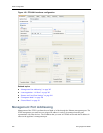

Interface Configuration
EncrypTight User Guide 307
preserves the network addressing of the protected network by copying the original source IP and MAC
addresses from the incoming packet to the outbound packet header.
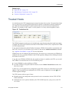
In transparent mode the ETEP’s remote and local ports are not viewable from a network standpoint. The
local and remote ports do not use user-assigned IP addresses. In Layer 3 IP networks the local and remote
ports cannot be contacted through an IP address, and they do not respond to ARPs. The ETEP is also
transparent in Ethernet networks when configured as a Layer 2 encryptor.
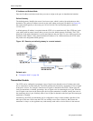
If you want to conceal the original source IP address when sending encrypted traffic, configure the ETEP
to operate in non-transparent mode. In non-transparent mode, the original source IP address in the
outbound packet header is replaced with either an IP address for the remote port or a virtual IP address.
The ETEP port MAC address is used as the packet’s source MAC address. You must assign IP addresses
to the local and remote ports when configuring the ETEP for this mode of operation.
Non-transparency settings apply only when the ETEP is configured for Layer 3 operation and being used
in a distributed key policy that uses a virtual IP address or remote IP address.
Related topics:
● “Network Addressing for IP Networks” on page 35
● “Addressing Mode” on page 185
● “Local and Remote Port IP Addresses” on page 307
● “Encryption Policy Settings” on page 334
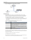
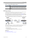
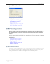
Local and Remote Port IP Addresses
When transparent mode is disabled, you need to assign an IP address, subnet mask, and default gateway
to the local and remote ports. The remote port connects the ETEP to an untrusted network, which is
typically a WAN, campus LAN, or MAN. The local port IP address identifies the ETEP to the device on
the local side of the network, such as a server or a switch.
NOTE
If you change the remote IP address on an ETEP that is already deployed in a policy, you must redeploy
your policies after the new configuration is pushed to the appliance.
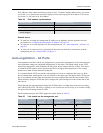
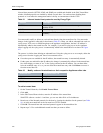
Table 87 When to use transparent mode
Policy Type Mode of operation
Layer 2 policies (distributed key mesh and stand-alone point-to-point) Transparent mode
Layer 3 distributed key policy:
Copy the original source IP address to the encryption header
Transparent mode
Layer 3 distributed key policy:
Conceal the original source IP address and replace it with one of the
following:
• ETEP remote port IP address. This forces traffic through a specific
ETEP.
• User defined virtual IP address. This is useful for load balanced traffic
over a private data network, or when sending traffic over the public
internet.
Non-transparent mode