


Installation
8
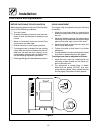
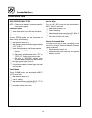
Plumbing Connections
WATER CONNECTION
NOTE: Hot water maximizes steam production
but is not required. Cold water may be
supplied to both inlets if hot water is not
available.
BC-20G --- Connect the a ppl iance to q ual ity col d
water v ia a pressure hose with 3 /4” (1/9 cm) cou-
plings. Cold water is connected to the left soleno id/
pressure regulator as viewed from the rear o f the
oven. Hot water connection, right solenoid/pressure
regulator, to the boil er is recommended. A shut off
valvemustbeprovidedadjacenttotheoven.
NOTE: Hot water must n o t be applie d to th e cold
water inlet .
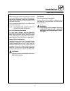
1/2” Appliance Hose
With 3/4” Hose Fittings
Figure 2
WARNING!!
The use of poor quality water will invali-
date your warranty.
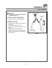
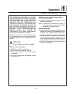
DRAIN CONNECTION
A 2” (5 cm) copper pipe with standard drain pitch
mustberuntoanopendrainorconnectedtoa
standpipe equipped with a vent.
NOTE: Thewastewatercanalsobedirectedtoa
nearby floor drain. Flexible hose which al-
lows trapped water to accumulate in
sagged runs must be avoided.
1. Find the drain connection on the lower rear of
the unit.
2. Loosen the coupling clamps. Attach a 2” (5
cm) copper drain pipe to the drain connection.
Retighten t he coupling clamps.
NOTE: The open end of the drain should be in-
stalled facing the floor. Copper line, used
for installation to an open drain or floor
sink, must be supplied by the installer.Use
of a trap inline will cause drain backup.
2” Drain
Customer
Supplied
To Drain
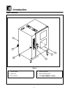
Oven
Drain
Figure 3
Specific water/drain connection for City of Los
Angeles
1. Each drain line fro m the appliance shall be
routedwithoutdipsorsagstoterminateabove
the flood level rim of an approved indirect waste
receptor.
2. The appliance shall be installed in accordance
with the manufacturer’s printed instructions
and the LAPC and LAMC, 1999 editions.
3. A backflow protection device may b e required
by lo cal c o des. If so, instal l on the potable water
system directl y ahead of the appliance. The
backflow protection device shall b e any of the
foll o wing: a n approv ed pressure type v acuum
breaker i nstall ed at least 12” above the highest
point of use, a double check valve backflow pre-
venter or a reduced pressure principal backfl o w
preventer.