


Machine Alignment (Open-Drive Machines)
Alignment Methods
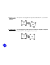
There are several established procedures for aligning shafts. The dial indicator method is
presented here since it is considered to be one of the most accurate and reliable. Another faster
and easier method for alignment involves the use of laser alignment tools and computers.
Follow the laser tool manufacturer’s guidelines when using the laser technique.
Where job conditions such as close-spaced shafts prohibit the use of dial indicators for
coupling face readings, other instruments such as a taper gage may be used. The same
procedures described for the dial indicator may be used with the taper gage.
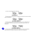
Shafts placed in perfect alignment in the nonoperating (cold) condition will always move out
of alignment to some extent as the machine warms to operating temperature. In most cases,
this shaft misalignment is acceptable for the initial run-in period before hot check and alignment
can be made (see Hot Alignment Check section.)
General
1.
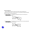
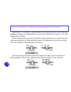
Final shaft alignment must be within .002-in. TIR (Total Indicated Runout) in parallel.
Angular alignment must be within .00033 inches per inch of traverse across the coupling
face (or inch of indicator swing diameter)
at operating temperatures
. For example, if a
bracket-mounted indicator moves through a 10-in. diameter circle when measuring angular
misalignment, the allowable dial movement will be 10 times .00033 for a total of .0033
inches.